
Power distribution cabinet

A technology for power distribution cabinets and cabinets, which is applied to substation/power distribution device shells, electrical components, substation/switch layout details, etc., and can solve problems such as poor dustproof performance of power distribution cabinets, poor heat dissipation performance of devices, and life-threatening problems , to avoid dust entry, easy maintenance, and good heat dissipation

Inactive Publication Date: 2017-03-22
国网山东济南市长清区供电公司 +1
View PDF0 Cites 6 Cited by
  • Summary
  • Abstract
  • Description
  • Claims
  • Application Information

AI Technical Summary

Problems solved by technology

[0002] With the advancement of science and technology and the improvement of technical level, the design of power distribution cabinets is becoming more and more scientific. Many power distribution cabinets are equipped with corresponding heat dissipation structures and preventive mechanisms in order to improve their performance. However, the distribution cabinets in the prior art The following two problems generally exist in the electric cabinet: 1. Since the power distribution cabinet is generally used to load multiple lines, the interior of the power distribution cabinet in the prior art is generally an integrated structure, and it is easy to install after multiple lines go in. It will cause confusion. Once the line is chaotic, it will be dangerous, and even threaten people's lives. 2. Since the power distribution cabinets are generally installed under the eaves or hung on the outer wall, once the rainstorm comes in summer, special To protect the power distribution cabinet against rain, in order to solve the above problems, there is an existing power distribution cabinet, but this kind of power distribution cabinet has poor dustproof performance, and the installation of the device components is compact, which leads to poor heat dissipation performance of the device

Method used


Image

  • Power distribution cabinet

Examples


Embodiment Construction

[0012] The following will clearly and completely describe the technical solutions in the embodiments of the present invention with reference to the accompanying drawings in the embodiments of the present invention. Obviously, the described embodiments are only some, not all, embodiments of the present invention. Based on the embodiments of the present invention, all other embodiments obtained by persons of ordinary skill in the art without making creative efforts belong to the protection scope of the present invention.

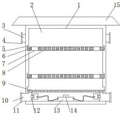
[0013] see figure 1 In an embodiment of the present invention, a power distribution cabinet includes a cabinet body 1, an installation cavity 2 and a rain-proof roof 15, the top of the cabinet body 1 is provided with a rain-proof roof 15, and the cabinet body 1 is provided with an installation cavity 2, Installation cavity 2 is provided with installation plate 6, and the quantity of installation plate 6 is more than one, and installation plate 6 just divides i...


PUM


Abstract

The invention discloses a power distribution cabinet, which comprises a cabinet body, an installation cavity and a rain top, wherein the rain top is arranged at the top of the cabinet body; the installation cavity is arranged in the cabinet body; an installation plate is arranged in the installation cavity; communication holes are arranged in the surface of the installation plate; wiring holes are arranged in the left side and the right side of the installation plate; an installation groove matched with the installation plate is arranged in the inner wall of the installation cavity; a bottom plate is arranged at the bottom of the installation cavity; air outlets are arranged in the left outer wall and the right outer wall of the cabinet body at the lower part of the bottom plate; air inlets are arranged in the outer wall of the cabinet body at the upper sides of the air outlets; each air inlet is provided with a dust hood; an exhaust fan is arranged at an internal port of each air outlet and is connected with a motor controller; and the motor controller is connected with a temperature sensor. The power distribution cabinet is simple and reasonable in structure, good in heat dissipation performance and convenient to repair; and meanwhile, the dust is also prevented from entering the power distribution cabinet.

Description

technical field [0001] The invention relates to electric equipment, in particular to a power distribution cabinet. Background technique [0002] With the advancement of science and technology and the improvement of technical level, the design of power distribution cabinets is becoming more and more scientific. Many power distribution cabinets are equipped with corresponding heat dissipation structures and preventive mechanisms in order to improve their performance. However, the distribution cabinets in the prior art The following two problems generally exist in the electric cabinet: 1. Since the power distribution cabinet is generally used to load multiple lines, the interior of the power distribution cabinet in the prior art is generally an integrated structure, and it is easy to install after multiple lines go in. It will cause confusion. Once the line is chaotic, it will be dangerous, and even threaten people's lives. 2. Since the power distribution cabinets are generally...

Claims


Application Information

Patent Timeline
IPC IPC(8): H02B1/28H02B1/56
CPCH02B1/28H02B1/565
Inventor 郭映歧焦艳艳陶殿军于子恒
Owner 国网山东济南市长清区供电公司
Learn More