
a dishwasher
A dishwasher and casing technology, applied in the field of home appliances, can solve the problems of increasing the resistance of the user to open the door, hindering the buffering force, and the heavy weight of the dishwasher door, so as to save energy
- Summary
- Abstract
- Description
- Claims
- Application Information
AI Technical Summary
Problems solved by technology
Method used
Image

Examples
Embodiment 1
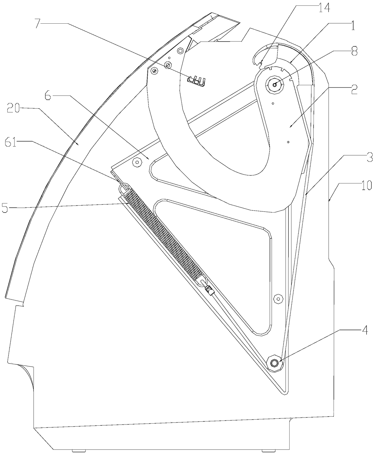
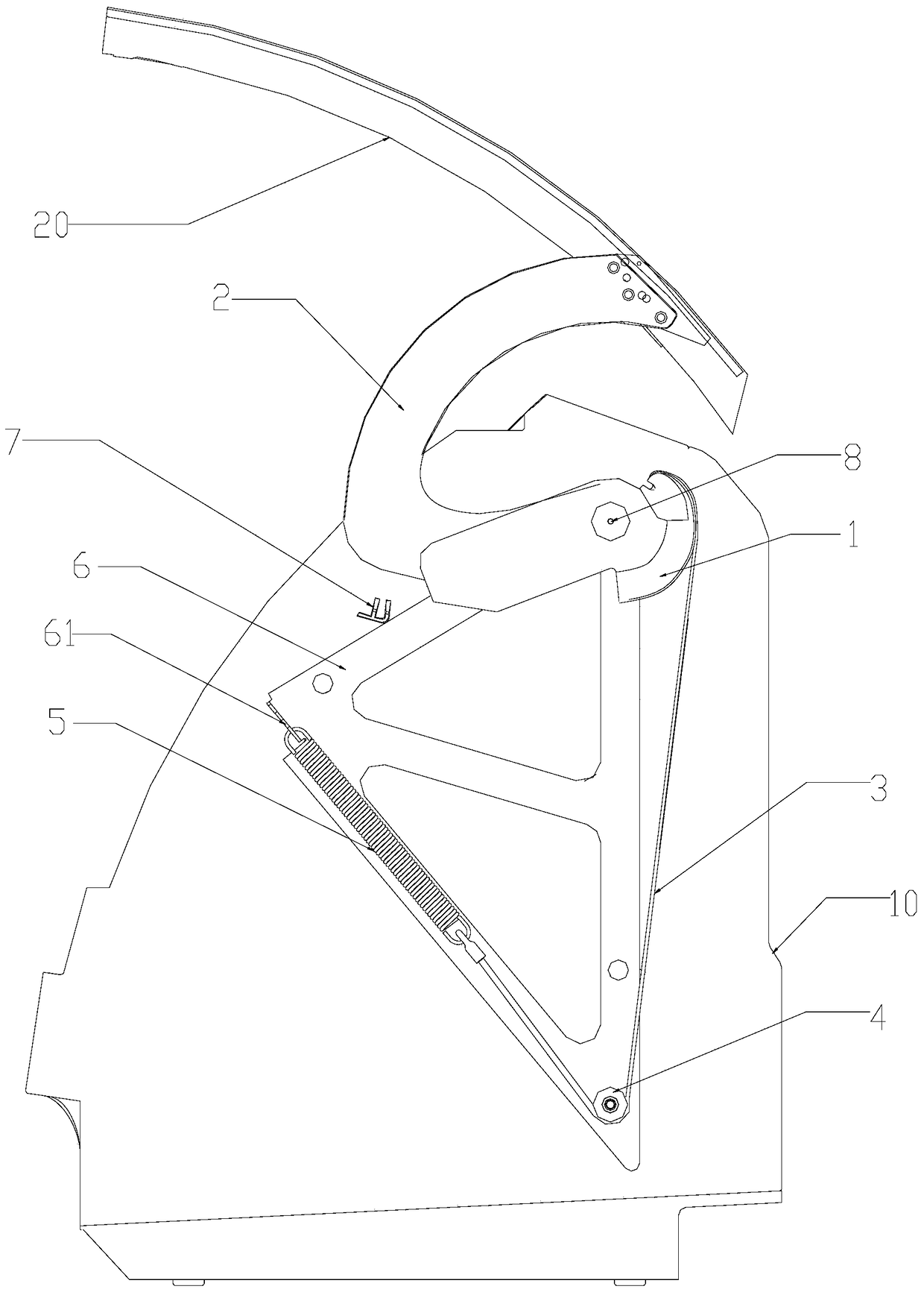
[0040] Such as figure 1 and figure 2 As shown, in this embodiment, a door installation structure of a dishwasher is introduced, which includes a spring 5 in an elongated state, one end of the spring 5 is connected to the bracket 6, and the other end is connected to the door 20 through the pull cord 3 connect. The door 20 is provided with or installed with a cam part 1 that rotates around the axis with the door 20. The cam part 1 has an arc-shaped outer side 18 concentric with the door axis, and the arc-shaped side of the pull cord 3 and the cam part 1 The outer sides 18 are connected at one end.
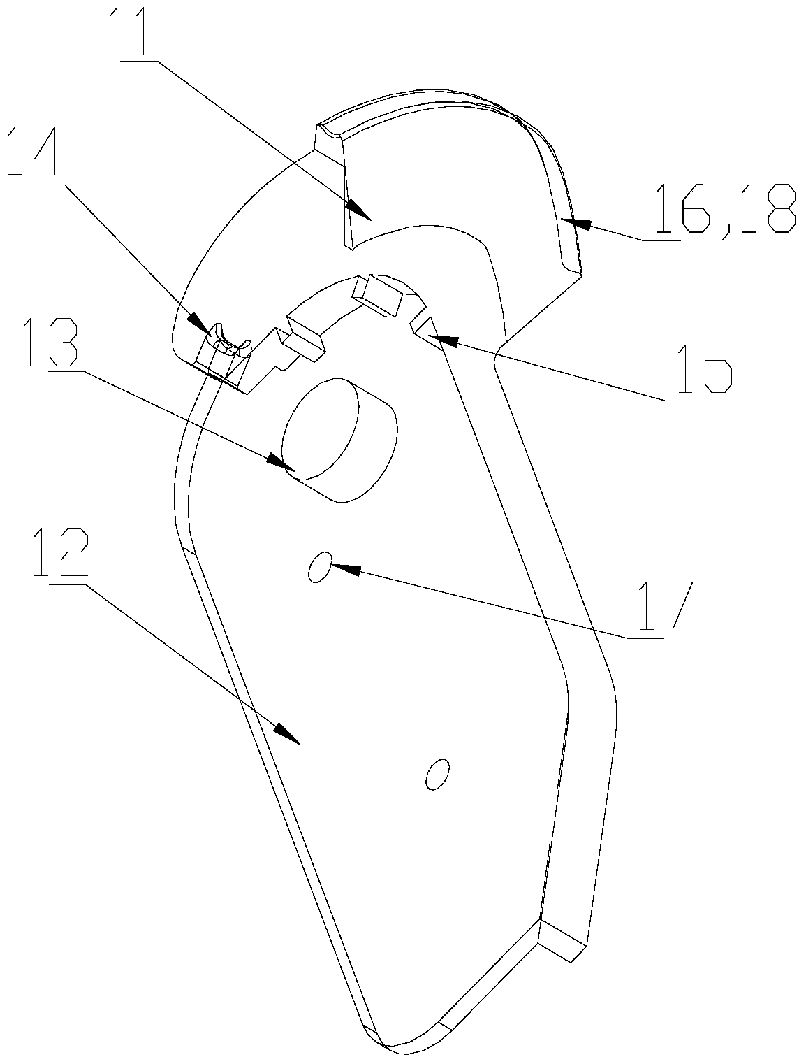
[0041] In this embodiment, the arc-shaped outer side 18 of the cam part 1 is arranged above the door shaft and on the side away from the door; 14 of the hanging slots. Preferably, the arc-shaped outer side 18 of the cam part 1 is provided with a chute 16 arranged along a vertical plane for the installation of the pull cord 3, so as to avoid horizontal sliding of the chute relati...
Embodiment 2
[0048] Such as figure 1 and figure 2 As shown, in this embodiment, the support 6 is a triangular tripod, the rear side of the tripod is set close to or attached to the rear side of the housing 10, the spring 5 extends along the lower side of the tripod, and the lower side of the tripod A fixed pulley 4 guiding the direction of the stay cord 3 is provided at the junction of the side and the rear side, and one end of the spring 5 away from the fixed pulley 4 is connected with the tripod, and the other end is connected with the stay cord 3 . The hinge 8 connecting the door 20 with the bracket 6 is at the upper end of the tripod.
[0049] By arranging the bracket 6 as a triangle, and setting the spring 4 and the hinge 5 at different sides of the triangle bracket 6, the position arrangement of each component of the installation structure is rationalized, especially the length of the space where the spring is located is relatively large, so as to be suitable for Because of the in...
Embodiment 3
[0052] Such as Figure 4 As shown, in this embodiment, the lower side of the bracket 6 is provided with a plurality of grooves 61 for hanging the ends of the spring 5 along the axial direction of the spring 5, and there is a certain distance between each groove 61 to adjust the spring. 5 to achieve the purpose of correspondingly adjusting the opening and pausing angle of the dishwasher door.
[0053] Preferably, in this embodiment, the lower side of the bracket 6 is inclined upward from the rear side of the housing 10 toward the door 20 , and a plurality of grooves 61 at a certain distance are provided near the upper end of the lower side of the bracket 6 . Therefore, the spring 5 is installed on the front end of the bracket 6, so that the user or installer can install the spring conveniently.
PUM
 Abstract
Description
Claims
Application Information