Conveying device

A conveying device and conveying mechanism technology, applied in the direction of conveyors, conveyor objects, mechanical conveyors, etc., can solve problems such as negative impacts on the next process, mechanical accidents, etc., to improve production efficiency, not easily damaged, and reduce impact force Effect

Active Publication Date: 2013-12-25
HANGZHOU ZHONGYA MACHINERY CO LTD
View PDF7 Cites 16 Cited by
  • Summary
  • Abstract
  • Description
  • Claims
  • Application Information

AI Technical Summary

Problems solved by technology

Excess products in the mold box will have a negative impact on the next process, and in severe cases, mechanical accidents will occur

Method used


Image

  • Conveying device
  • Conveying device
  • Conveying device

Examples


Embodiment Construction

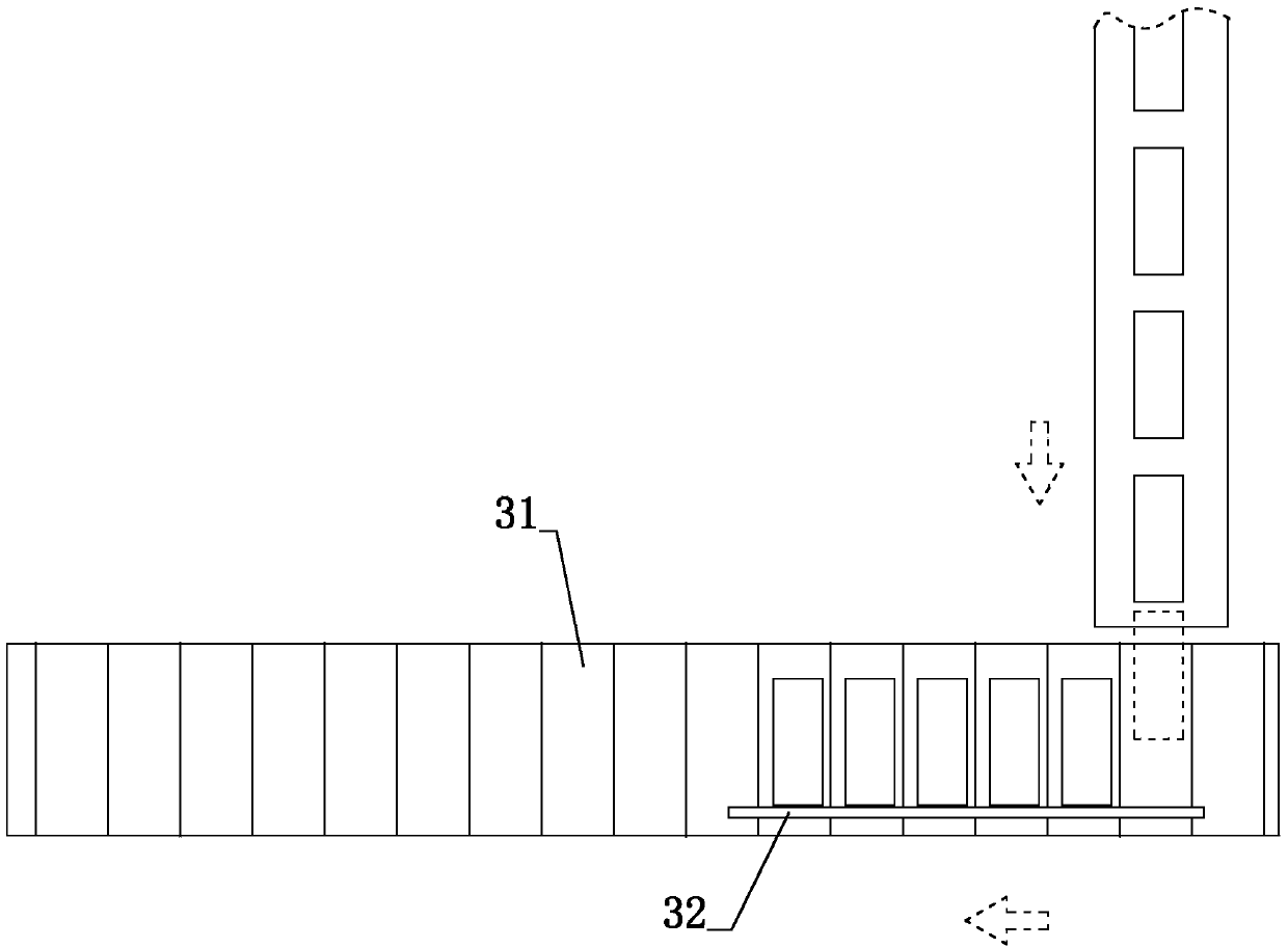
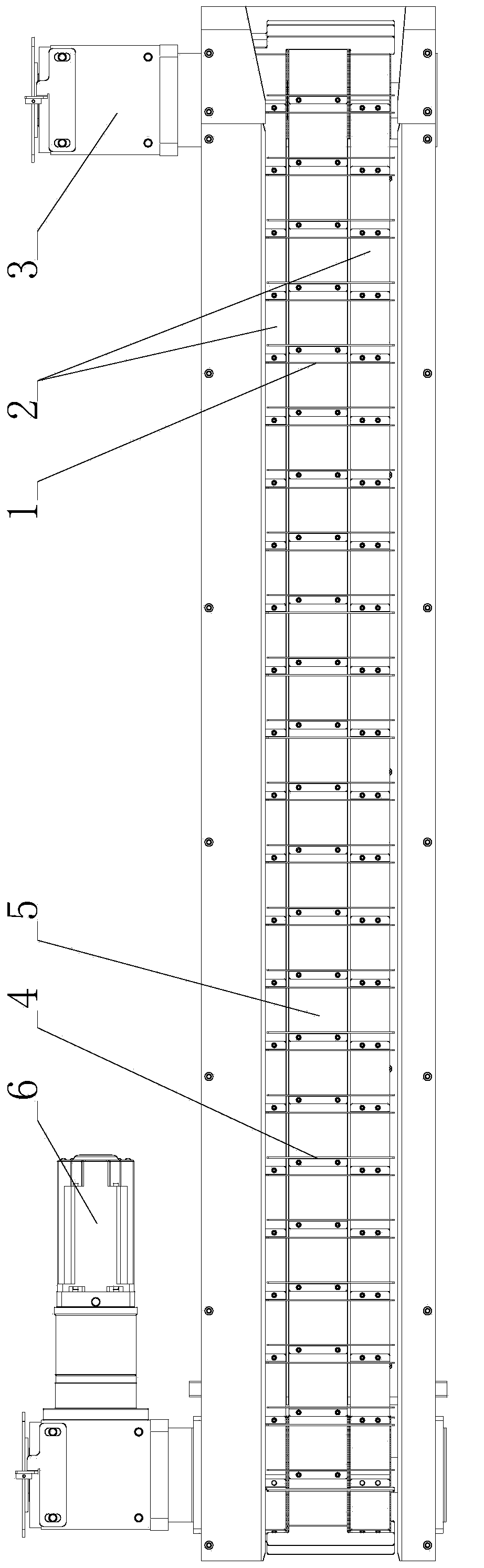
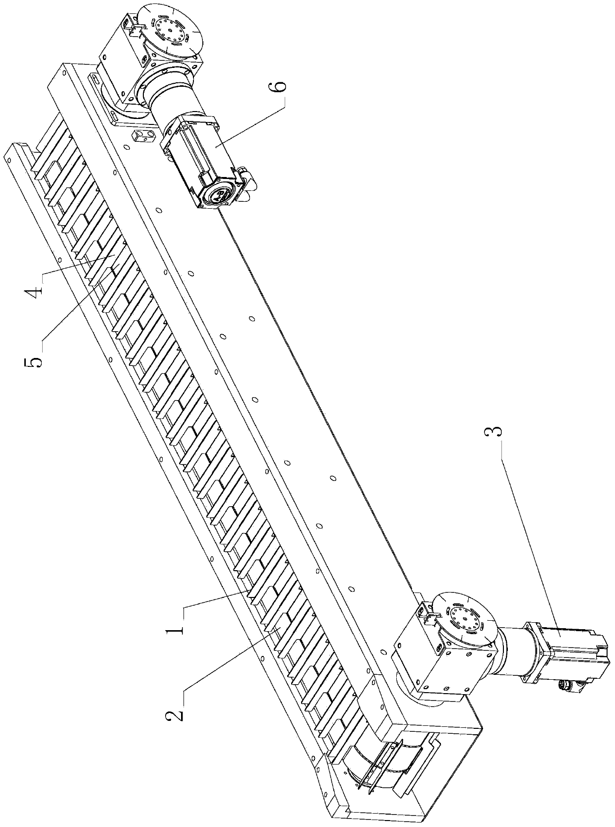
[0028] Such as figure 2 , 3 As shown, the circular arrangement mechanism includes a first conveying mechanism, a second conveying mechanism and a frame.

[0029] The first conveying mechanism comprises the first baffle plate 1, two first driving pulleys, two first driven pulleys, two first synchronous belts 2 and a first servo motor 3; the second conveying mechanism comprises the second Baffle plate 4, a second driving pulley, a second driven pulley, a second synchronous belt 5 and a second servo motor 6. Two parallel rotating shafts are installed on the frame, including a first rotating shaft and a second rotating shaft, and the rotating shafts are all movably installed on the frame through bearings.

[0030] The first driving pulley is fixedly installed on the first rotating shaft, the first rotating shaft is provided with a keyway, the first driving pulley is also provided with a keyway, and the first driving pulley and the first rotating shaft are fixed by inserting a k...


PUM


Abstract

The invention discloses a conveying device. The conveying device comprises a circulatory arranging mechanism, a direction changing conveying mechanism and a product conveying mechanism. The circulatory arranging mechanism is arranged on one side of the product conveying mechanism; the direction changing conveying mechanism is arranged above the circulatory arranging mechanism and the product conveying mechanism; the direction changing mechanism provided with a pushing area which conveys products on the product conveying mechanism into the direction changing conveying mechanism, and the pushing area faces towards the circulatory arranging mechanism and the product conveying mechanism; both the conveying direction of the circulatory arranging mechanism and the conveying direction of the direction changing conveying mechanism are perpendicular to the conveying direction of the product conveying mechanism. According to the conveying device, products can be conveyed at low speed from an original conveying line to arranging stations, so that the collision strength between the products and the conveying units can be effectively reduced to protect the products from damage.

Description

technical field [0001] The invention relates to a delivery device. Background technique [0002] The products are arranged one by one on the conveyor belt, and at a specific working position, the products will be transported into the mold box that acts as an arrangement. The mold boxes 31 are distributed in rows on the conveying mechanism, and the mold boxes do cyclical movement when the conveying mechanism works. Such as figure 1 As shown, the product is pushed into the mold box opposite to the conveyor belt on the conveyor belt, and then the conveying mechanism where the mold box is located rotates, driving the mold box with the product forward for a certain distance in the conveying direction, thereby making the adjacent mold box Connect to the conveyor belt. The product is driven by the conveyor belt at a high speed. When it enters the mold box along the conveying direction, it is affected by its own inertia, and the moving speed of the product is still relatively fas...

Claims


Application Information

Patent Timeline
Patent Type & Authority Applications(China)
IPC IPC(8): B65B35/44B65G37/00B65G47/52B65G47/30B65G15/58
Inventor 史中伟姚辉
Owner HANGZHOU ZHONGYA MACHINERY CO LTD
Why Eureka
Try Eureka