
Subframe fatigue test bending moment, torque elimination device

A fatigue test, sub-frame technology, applied in the direction of measuring device, vehicle test, mechanical component test, etc., can solve problems such as damage to the drive shaft, high cost, damage to the sensor, etc., to avoid installation distance, reduce installation difficulty, Accurate test results

Inactive Publication Date: 2019-05-10
GUANGXI UNIVERSITY OF TECHNOLOGY
View PDF5 Cites 0 Cited by
  • Summary
  • Abstract
  • Description
  • Claims
  • Application Information

AI Technical Summary

Problems solved by technology

In addition, in the prior art, when carrying out the longitudinal fatigue strength test of the sub-frame, the transmission shaft between the workpiece, the sensor, and the actuator (power source) needs to be strictly on the same straight line, although the existing adjustment device has achieved a high Accuracy, but it is difficult and costly to achieve strict collinearity, and it is even impossible to achieve true collinearity. The drive shafts cannot be strictly collinear so that there is bending moment and torque between their drive shafts, even if the bending moment or rotation The moment is very small, but under the conditions of the strength and number of experiments in the fatigue strength test and other experiments, the harm caused by the bending moment is magnified, ranging from damage to the transmission shaft, to damage the sensor, and at the same time reducing the service life of the fatigue strength test device and The test accuracy reduces the efficiency of the test and greatly increases the cost of the fatigue strength experiment

Method used


Image

  • Subframe fatigue test bending moment, torque elimination device
  • Subframe fatigue test bending moment, torque elimination device
  • Subframe fatigue test bending moment, torque elimination device

Examples


Embodiment 1

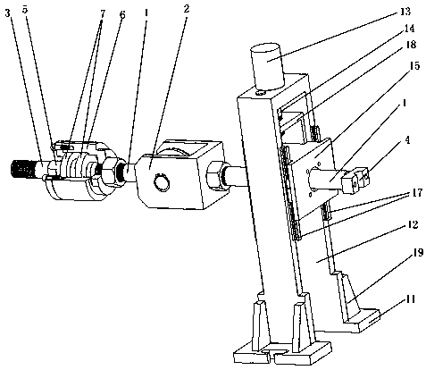
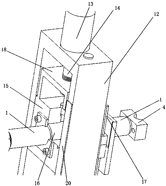
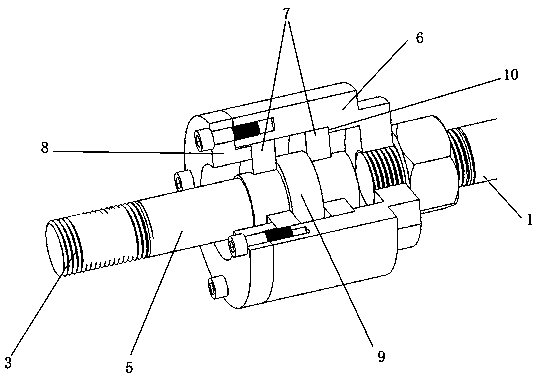
[0030] like Figure 1-3 As shown, the subframe fatigue test bending moment and torque elimination device provided in this embodiment include a main shaft 1, a height adjustment device, a universal joint 2, a transmission shaft 3, and a torque elimination device;

[0031] The main shaft 1 is installed on the height adjustment device, and can move up and down in the vertical direction under the action of the height adjustment device;

[0032] The two ends of the main shaft 1 are divided into two sides located on the height adjustment device, the front end of the main shaft 1 is provided with a universal joint 2, and the rear end of the main shaft 1 is provided with a workpiece connection part 4;

[0033] The torque elimination device is connected with the universal joint 2 through the main shaft 1, and the other end of the torque elimination device is connected with the transmission shaft 3;

[0034] The torque elimination device includes a shaft 5, a sleeve 6, a tapered roller...


PUM


Abstract

The invention aims at providing an auxiliary frame fatigue test bending moment and torque elimination device comprising a spindle, a height adjusting device, a universal joint, a transmission shaft and a torque elimination device. The spindle is installed on the height adjusting device and can perform elevating motion along a vertical direction under the effect of the height adjusting device. The two ends of the spindle are arranged at the two sides of the height adjusting device. The front end of the spindle is provided with the universal joint, and the rear end of the spindle is provided with a workpiece connecting part. The torque elimination device is connected with the universal joint through the spindle. The other end of the torque elimination device is connected with the transmission shaft. The defects in the prior art can be overcome by the device, and the device has the characteristics of eliminating the bending moment and the torque and enhancing the service life and the test accuracy.

Description

technical field [0001] The invention relates to the field of fatigue testing devices, in particular to a bending moment and torque eliminating device for subframe fatigue testing. Background technique [0002] The subframe can be regarded as the skeleton of the front and rear axles, and is an integral part of the front and rear axles. The sub-frame is not a complete frame, but only supports the front and rear axles, the suspension passes through it and then connects with the "positive frame", which is customarily called "sub-frame". The function of the subframe is to block vibration and noise and reduce its direct entry into the compartment; as an important part of the chassis, the subframe is subjected to complex stress conditions and bears various types of loads, including static force, impact, and alternating loads . Therefore, it is very important to analyze and check its strength and fatigue strength. In addition, in the prior art, when carrying out the longitudinal ...

Claims


Application Information

Patent Timeline
Patent Type & Authority Patents(China)
IPC IPC(8): G01M17/007G01M13/00
CPCG01M13/00G01M17/007
Inventor 尹辉俊官勇健曹稚英李鹏宇张婷婷
Owner GUANGXI UNIVERSITY OF TECHNOLOGY
Learn More