A kind of manufacturing method of rotary self-riveting forming motor rotor core

A technology of rotor iron core and motor rotor, which is applied in the manufacture of motor generators, stator/rotor bodies, electromechanical devices, etc. It can solve problems such as the inability to eliminate jumping, reduce the quality of the iron core, and large motor noise and vibration. Mechanical finishing process, improved service life, uniform effect of rotor magnetic circuit

Active Publication Date: 2019-04-05
浙江迪贝电气股份有限公司
View PDF6 Cites 0 Cited by
  • Summary
  • Abstract
  • Description
  • Claims
  • Application Information

AI Technical Summary

Problems solved by technology

[0007] 1. There is a thickness difference in the stamping material of cold-stamped silicon steel sheet. The cumulative error generated during the lamination process of the rotor punching sheet leads to a certain height deviation at both ends of the formed rotor core. Due to the rotation angle of the rotor punching sheet after punching and riveting Extremely small, unable to fully and effectively eliminate the height deviation at both ends of the rotor core, resulting in unevenness at both ends of the rotor core;
[0008] 2. Due to the insurmountable precision problems of the stamping die, there are precision errors in the inner and outer circle dimensions and groove dimensions of the rotor punching sheet, resulting in a certain shape and position deviation of the stacked riveted rotor core, resulting in a radial dimension runout deviation of the rotor. Large, the radial imbalance is too large, resulting in uneven magnetic circuit of the rotor core;
[0009] 3. Since the cold-rolled silicon steel sheet is formed by rolling, the rolling direction and transverse magnetic properties (magnetic conduction) are inconsistent, which also makes the magnetic circuit of the rotor core uneven
[0010] To sum up, ①When the rotor rotates at high speed, it will inevitably lead to large noise and vibration of the motor, which will reduce the service life of the motor; ②Because the beating caused by the inner and outer circles of the rotor core cannot be eliminated, it is necessary to add mechanical finishing processes , that is, grinding the inner and outer circles. This supplementary processing not only wastes man-hours but also reduces the quality of the iron core and deteriorates the performance of the motor.

Method used


Image

  • A kind of manufacturing method of rotary self-riveting forming motor rotor core
  • A kind of manufacturing method of rotary self-riveting forming motor rotor core
  • A kind of manufacturing method of rotary self-riveting forming motor rotor core

Examples


Embodiment 1

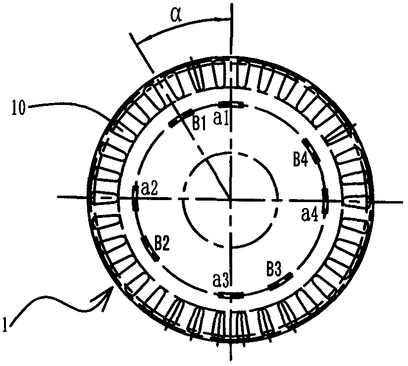
[0055] The illustration of the present embodiment, the adopted material thickness is roughly the bar of d=0.5mm, and the number n=100 of annular rotor punching sheets 1 (the number n of the rotor punching sheets 1 whose sheet thickness is definite is made of rotor iron. The core stack height is determined by the stack height of the rotor core (H = 50mm), and the slots of the rotor core and stator core to be manufactured are matched as follows: the number of guide slots for the rotor core Q = 34, and the stator core The number of embedding slots Z=24.

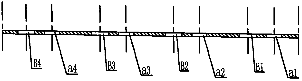
[0056] Please refer to Picture 1-1 , 1-2 , 1-3, 2-1, 2-2, 2-3, 2-4, 3-1, 3-2, 3-3, 3-4, 4-1, 4-2, 4-3, 4 As shown in -4, the rotor core is formed by continuously punching and riveting 100 ring-shaped rotor punching pieces 1 automatically and continuously on the punching die with continuously conveyed strips. The punching process of the rotor punching 1 includes Sequentially punching the inner circle together with the guide bar ...

Embodiment 2

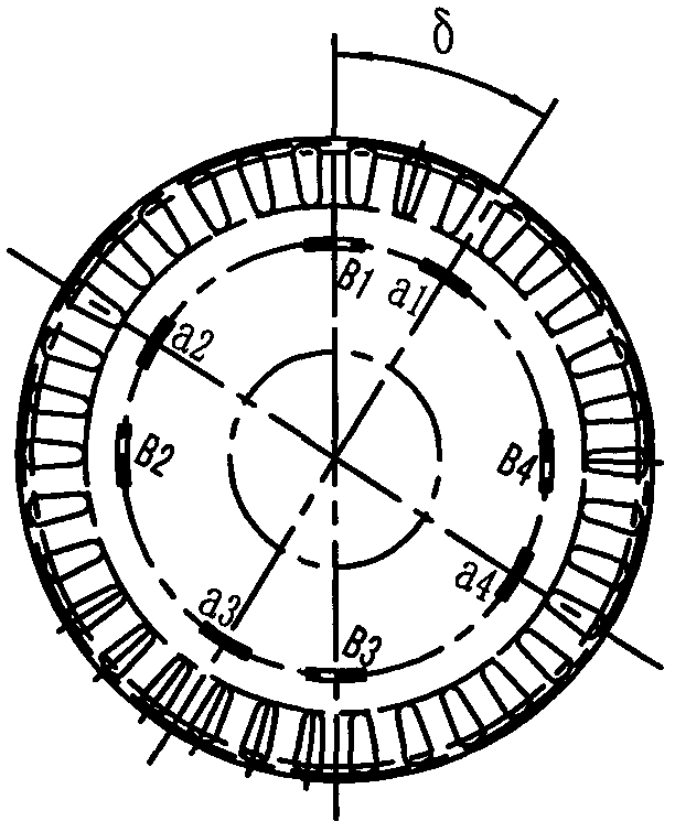
[0081] The illustration of the present embodiment, the adopted material thickness is roughly the bar of d=0.5mm, and the number n=100 of annular rotor punching sheets 1 (the number n of the rotor punching sheets 1 whose sheet thickness is definite is made of rotor iron. The stack height of the rotor core is determined by the stack height of the rotor core (H = 50mm). The slots of the rotor core and the stator core to be manufactured are matched as follows: The number of slots Z=24.

[0082] Please refer to Figure 5-1 , 5-2 , 5-3, 6-1, 6-2, 6-3, 6-4, 7-1, 7-2, 7-3, 7-4, 8-1, 8-2, 8-3, 8 As shown in -4, the rotor core is formed by continuously punching and riveting 100 ring-shaped rotor punching pieces 1 automatically and continuously on the punching die with continuously conveyed strips. The punching process of the rotor punching 1 includes Sequentially punching the inner circle together with the guide bar grooves 10 evenly spaced, punching the rivets together with the thro...


PUM


Abstract

The invention discloses a manufacturing method for a rotary automatically-riveted formed motor rotor iron core. The manufacturing method for n pieces of rotor punching sheets comprises the steps of punching inner circles and guiding strip grooves, rivet sheets and through holes in sequence, and punching outer circles, pressing and riveting and laminating, wherein the numbers of the stator iron core grooves and the rotor iron core grooves are Z and Q separately; each rotor punching sheet and the adjacent rivet sheet and the through hole are arranged in one group, and at least three groups are uniformly distributed in the circumferential direction; the included angle <alpha> between the centers of the rivet sheets and the centers of the corresponding through holes in each group is equal to 360 degrees / Q*q, wherein q is the number of the guiding strip grooves in the included angle; the punched and formed first rotor punching sheet rotates around the center clockwise for an angle of <delta>; after the rotor punching sheets are punched, pressed, riveted and connected piece by piece, all the obtained rotor punching sheets rotate for an angle of <delta>; and when the rotation angle <delta> is equal to <alpha>+360 degrees / Z / n, <alpha>-360 degrees / Z / n, and <delta>, a clockwise inclined groove rotor iron core, an anticlockwise inclined groove rotor iron core and a straight groove rotor iron core are obtained. The rotor iron core which is prepared by the steps of rotating, punching, laminating and riveting, and rotating circularly is flat in end plane; the inner circles and the outer circles and the groove shapes are high in precision; the shape and location deviation is low; and the rotor is low in vibration and free of noise.

Description

【Technical field】 [0001] The invention relates to a method for manufacturing a motor rotor iron core formed by rotating self-riveting, and belongs to the technical field of motor rotor manufacturing. 【Background technique】 [0002] In induction (single-phase asynchronous) motors, in order to weaken the additional torque and noise caused by the tooth harmonic magnetic field, the general cage rotor often uses inclined guide bar slots, that is, the guide bar slots are skewed by one degree relative to the stator along the shaft. angle. [0003] Now take the manufacturing of rotor core with four alternately evenly spaced through holes and rivets as an example to illustrate: [0004] The rotor core is formed by stacking 100 rotor punches. The rotor core and the stator core slots are matched as follows: the rotor core has 34 guide bar slots, and the stator core has 24 embedding slots. [0005] According to the requirements of the manufacturing process, the angle of the skewed rot...

Claims


Application Information

Patent Timeline
Patent Type & Authority Patents(China)
IPC IPC(8): H02K15/02
CPCH02K15/024
Inventor 邢懿烨王建鸿张小江马树江
Owner 浙江迪贝电气股份有限公司
Why Eureka
Try Eureka