Anode, and x-ray generating tube, x-ray generating apparatus, and radiography system using the same

A technology for generating devices and X-rays, which is applied in the parts of X-ray tubes, X-ray tubes, X-ray tube electrodes, etc. It can solve the problems of difficulty in ensuring X-ray output, inability to obtain tube current, etc., and achieve vacuum leakage suppression. Effect

Active Publication Date: 2017-03-22
CANON KK
View PDF6 Cites 1 Cited by
  • Summary
  • Abstract
  • Description
  • Claims
  • Application Information

AI Technical Summary

Problems solved by technology

[0004] In such an X-ray generating tube including a transmission target as an end window, when the X-ray generating operation is repeated, sometimes a desired tube current cannot be obtained and thus it is difficult to secure a necessary X-ray output

Method used


Image

  • Anode, and x-ray generating tube, x-ray generating apparatus, and radiography system using the same
  • Anode, and x-ray generating tube, x-ray generating apparatus, and radiography system using the same
  • Anode, and x-ray generating tube, x-ray generating apparatus, and radiography system using the same

Examples


no. 1 example

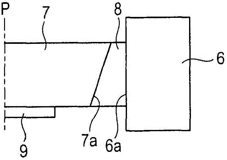
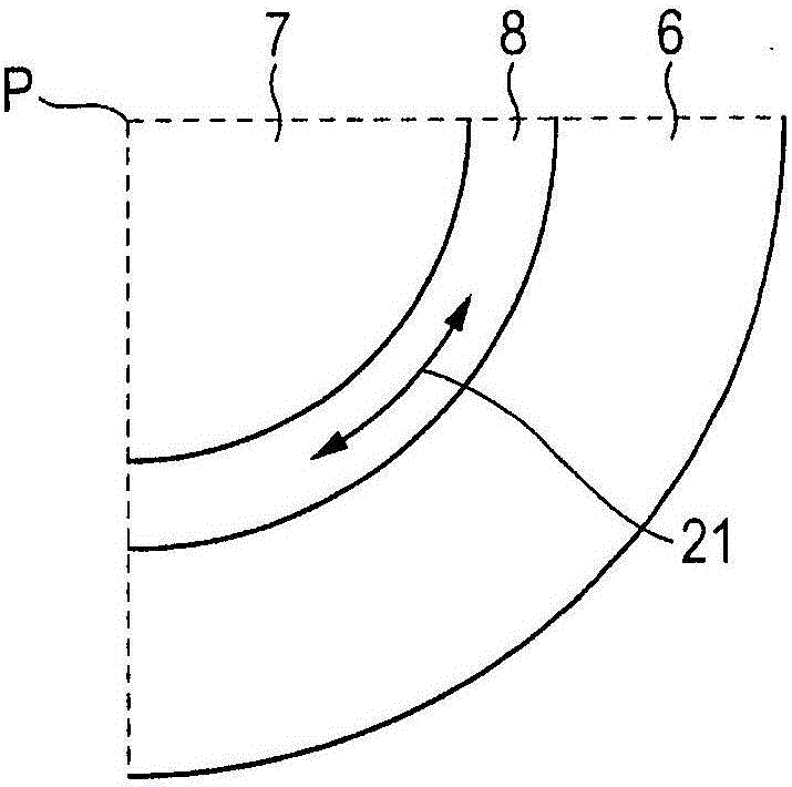
[0065] The anode 1 according to the first embodiment of the present invention is described. This example is a case in which the tubular anode member 6 is cylindrical and the transmissive substrate 7 of the target 10 is in the shape of a disc concentric with the inner circumference of the tubular anode member 6 in plan view. Such as Figure 1B As shown in , in the anode of the present invention, the bonding material 8 has a thickness that varies in a direction along the central axis P of the tubular anode member 6 (hereinafter referred to as “central axis P”). Note that in the present invention, the thickness of the bonding material 8 is the width of the bonding material 8 in a direction perpendicular to the central axis P of the tubular anode member 6, that is, in this case, the thickness of the bonding material 8 on the tubular anode member. 6 the width in the radial direction as well as in the transverse direction Figure 1B The paper width. Note that the bonding material...

no. 2 example

[0088] Figure 5 is a partial sectional view for schematically showing the structure of an anode according to another exemplary embodiment of the present invention. In this embodiment, the transmissive substrate 7 has a support surface 7 b for supporting the target layer 9 . Furthermore, the tubular anode member 6 has a tube inner circumference for supporting the transmissive substrate 7 . In addition, the tubular anode member 6 of this embodiment includes an annular protruding portion 41 protruding inward from the inner circumference of the tube in the direction of the tube diameter, which is the difference between the tubular anode member of this embodiment and the reference Figure 1A to Figure 3B The tubular anode member of the first embodiment described differs in that. The annular convex portion 41 has a bear surface 41a opposite to the outer periphery of the support surface 7b. The bonding material 8 extends from a gap in the tube axial direction extending in the tub...


PUM


Abstract

A thickness of a bonding material (8) is varied in a radial direction orthogonal to a central axis (P) of the tubular anode member (6), the bonding material (8) being used for bonding a transmitting substrate (7) for supporting a target layer (9) and a tubular anode member (6) in a direction along the central axis (P). Thus, a region in which a circumferential tensile stress of the bonding material (8) is alleviated is formed in the direction along the central axis (P) to prevent a crack from developing in the bonding material (8).

Description

technical field [0001] The present invention relates to an anode to be used in an X-ray generating tube and comprising a transmissive target, and also to an X-ray generating tube comprising the anode, an X-ray generating device comprising the X-ray generating tube, and a radiography system comprising the X-ray generating device. Background technique [0002] Transmission X-ray generating tubes comprising a transmission target are known. A transmission target uses X-rays emitted from its side, which is opposite the side where the electron beam enters the target. A transmission type X-ray generating tube may contain a target as an end window of the X-ray generating tube. Such a transmission type X-ray generating tube has advantageous features that the radiation angle can be made wider, the heat dissipation performance can be made higher, and the X-ray generating device can be downsized. A target in such a transmission type X-ray generating tube is hermetically bonded to a tu...

Claims


Application Information

Patent Timeline
Patent Type & Authority Applications(China)
IPC IPC(8): H01J35/08
CPCH01J2235/083H01J35/186H01J35/116G01N23/04H05G1/10H01J2235/086H01J35/12H05G1/02H05G1/025H01J35/02G01N2223/308H01J35/32H01J35/165H01J1/94H01J2237/032H01J2237/036H01J37/023H01J2235/085H01J2235/08H01J35/08
Inventor 大桥康雄上田和幸
Owner CANON KK
Why Eureka
Try Eureka