A trigger device of a pneumatic nail gun and the pneumatic nail gun

A technology of trigger device and air source device, which is applied in the direction of nailing tools and manufacturing tools, can solve the problems of low production efficiency, inability to apply automatic assembly line production, and high labor intensity of workers, and achieve the effect of simple structure of trigger device

Active Publication Date: 2018-12-28
苏州维与智能科技有限公司
View PDF7 Cites 0 Cited by
  • Summary
  • Abstract
  • Description
  • Claims
  • Application Information

AI Technical Summary

Problems solved by technology

[0002] In the wooden pallet production process, the nailing operation is manually operated by the worker holding a pneumatic nail gun. The trigger device of the pneumatic nail gun in the prior art includes a trigger body, a return spring and a piston. The return spring is connected to the trigger body and the piston respectively. When the pneumatic nail gun is in the standby state, the piston is blocked on the air flow channel inside the pneumatic nail gun. When nailing is required, the trigger body is manually pulled to drive the piston to move so that the piston is disengaged from the air flow channel, and the nailing operation is realized. This method of operation is labor-intensive for workers, and the production efficiency is low, and the pneumatic nail gun used for nailing in the prior art uses a plastic trigger for the trigger body, which cannot be applied to automatic assembly line production.

Method used


Image

  • A trigger device of a pneumatic nail gun and the pneumatic nail gun
  • A trigger device of a pneumatic nail gun and the pneumatic nail gun
  • A trigger device of a pneumatic nail gun and the pneumatic nail gun

Examples


Embodiment Construction

[0018] The technical solutions of the present invention will be further described below in conjunction with the accompanying drawings and specific embodiments.

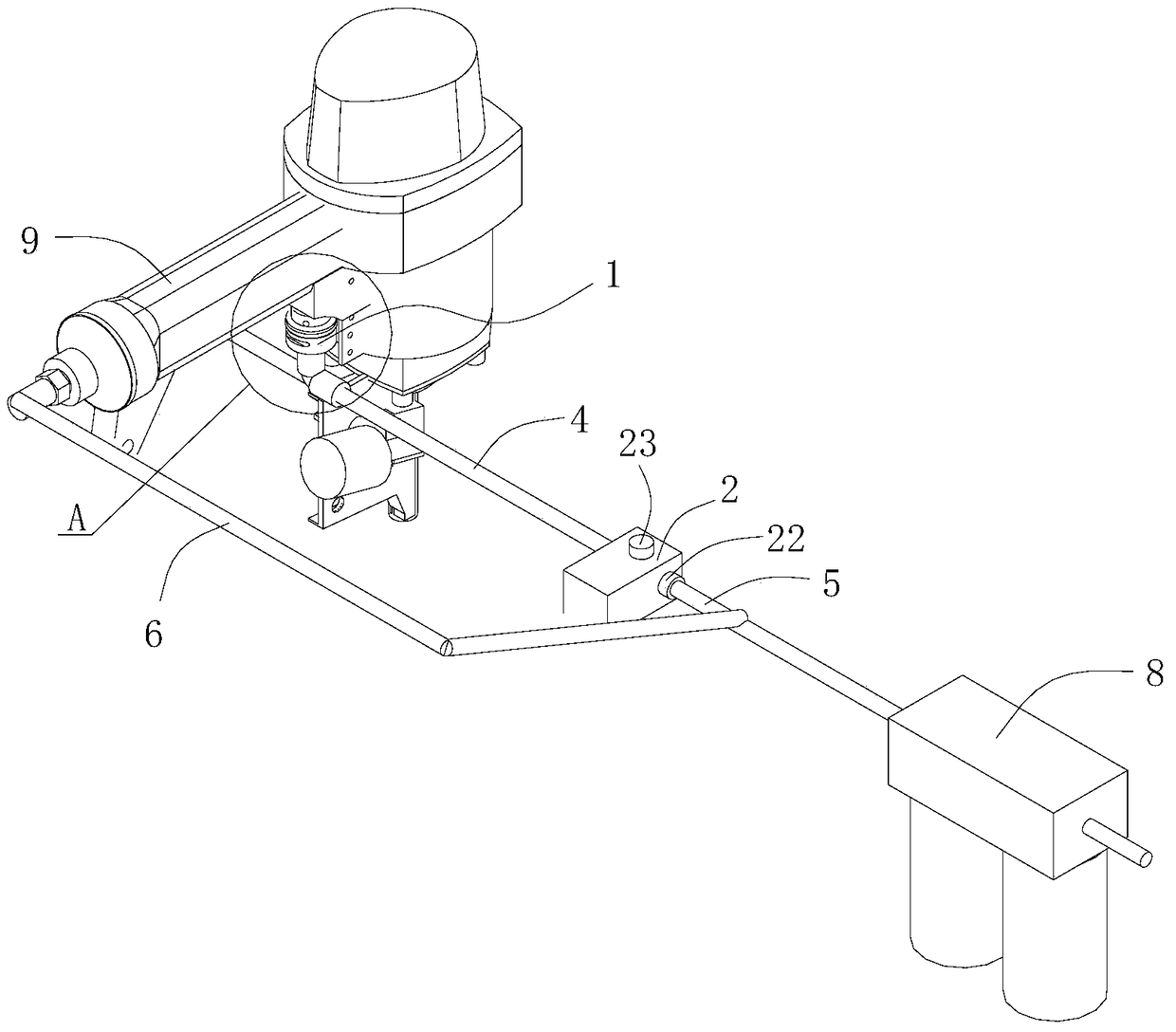
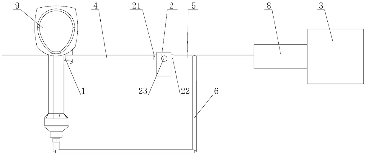
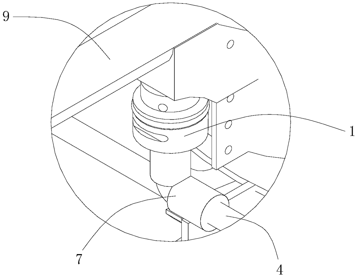
[0019] see Figure 1~Figure 3 As shown in the pneumatic nail gun, the pneumatic nail gun includes a pneumatic nail gun body 9 and a trigger device. The trigger device includes a trigger valve 1 and a solenoid valve 2. The trigger valve 1 communicates with the solenoid valve 2, and the solenoid valve 2 communicates with the air source of the pneumatic nail gun. Device 3 is connected.

[0020] Specifically, the trigger valve 1 is arranged on the pneumatic nail gun body 9, and the solenoid valve 2 is arranged outside the pneumatic nail gun body 9. In this embodiment, the solenoid valve 2 adopts a two-position three-way valve, and the trigger valve 1 is provided with a first One airflow passage, the pneumatic nail gun body 9 is provided with a second airflow passage, one end of the first airflow passage leads to the seco...


PUM


Abstract

The invention discloses a trigger device of a pneumatic nailer and the pneumatic nailer. The trigger device comprises a trigger valve and an electromagnetic valve. The trigger valve is arranged on a pneumatic nailer body and internally provided with a first airflow channel. The pneumatic nailer body is internally provided with a second airflow channel. One end of the first airflow channel leads to the second airflow channel, and the other end of the first airflow channel communicates with the electromagnetic valve through a first air pipe. The electromagnetic valve is connected with an air source device of the pneumatic nailer body through a second air pipe. The air source device communicates with the second airflow channel through a third air pipe. The trigger device is simple in structure, the pressure difference in the pneumatic nailer body can be controlled through the electromagnetic valve, so that automatic nailing is achieved through the pneumatic nailer controlled by an electric signal, and therefore the pneumatic nailer can be applied to automatic production line operation.

Description

technical field [0001] The invention specifically relates to the technical field of wood packaging, in particular to a trigger device of a pneumatic nail gun and the pneumatic nail gun. Background technique [0002] In the wooden pallet production process, the nailing operation is manually operated by the worker holding a pneumatic nail gun. The trigger device of the pneumatic nail gun in the prior art includes a trigger body, a return spring and a piston. The return spring is connected to the trigger body and the piston respectively. When the pneumatic nail gun is in the standby state, the piston is blocked on the air flow channel inside the pneumatic nail gun. When nailing is required, the trigger body is manually pulled to drive the piston to move so that the piston is disengaged from the air flow channel, and the nailing operation is realized. This kind of operation method has high labor intensity for workers and low production efficiency, and the pneumatic nail gun used...

Claims


Application Information

Patent Timeline
Patent Type & Authority Patents(China)
IPC IPC(8): B25C1/04
Inventor 吴彦晶
Owner 苏州维与智能科技有限公司
Why Eureka
Try Eureka