Belt breakage catching device of belt type conveyor

A broken belt capture device and belt conveyor technology, which is applied in the direction of conveyor control devices, conveyors, conveyor objects, etc., can solve the problem of sudden large capture force, easy damage to the belt, machine crash and death, etc. problems, to achieve the effect of convenient test and maintenance, low equipment cost, and simple device structure

Inactive Publication Date: 2017-03-29
BEIJING UNIV OF TECH
View PDF6 Cites 3 Cited by
  • Summary
  • Abstract
  • Description
  • Claims
  • Application Information

AI Technical Summary

Problems solved by technology

[0002] Belt conveyors are used in many fields. When a broken belt occurs on a belt conveyor, especially an inclined, long-belt, or large-capacity belt conveyor, it will cause long-term production stoppages and huge economic losses, even machine crashes. , the consequences are extremely serious
[0003] At present, there are many kinds of broken belt arresting devices for belt conveyors, but there are still the following problems: when catching the brake belt, some use line contact, the braking force is small, the braking force is concentrated, and it is easy to damage the belt; Contact, the arresting force reaches a large moment, and it is easy to damage the belt; existing similar products mainly use purely mechanical structures to solve these problems, but due to the harsh working environment of the broken belt catcher, the purely mechanical structure is often stuck due to rust If there is a failure due to mechanical action defects or other reasons, the problem of capture failure is prone to occur in the case of unmanned monitoring, thus affecting the working stability of the broken belt catcher

Method used


Image

  • Belt breakage catching device of belt type conveyor
  • Belt breakage catching device of belt type conveyor
  • Belt breakage catching device of belt type conveyor

Examples


Embodiment Construction

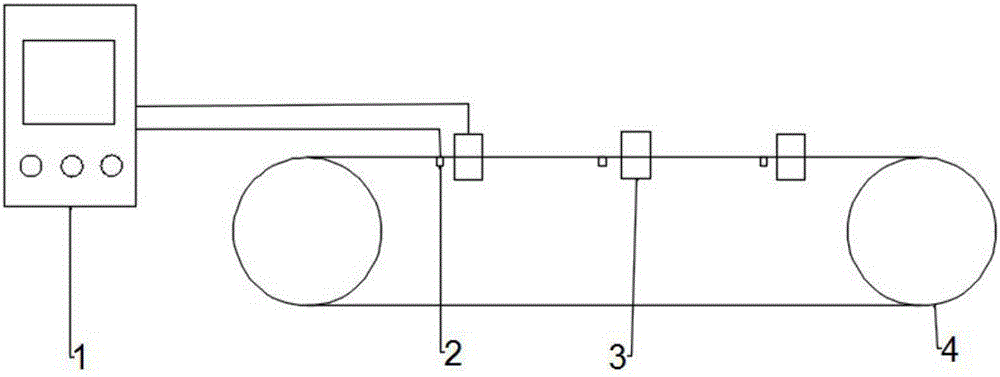
[0018] Depend on figure 1 As can be seen, the device of the present invention comprises a control host (1), a broken belt detection device (2) and a plurality of catching sub-stations (3), the control host and the catching sub-stations are connected by communication lines, and the control host is also connected with the catching sub-stations. The broken belt detection devices are connected, and the arresting substations are evenly arranged on the belt conveyor (4) at a certain interval. Each arresting substation is divided into a control unit and a mechanical execution unit, and the left and right sides of the mechanical execution unit are arranged symmetrically. , each side is composed of an upper catch mechanism and a lower catch mechanism.

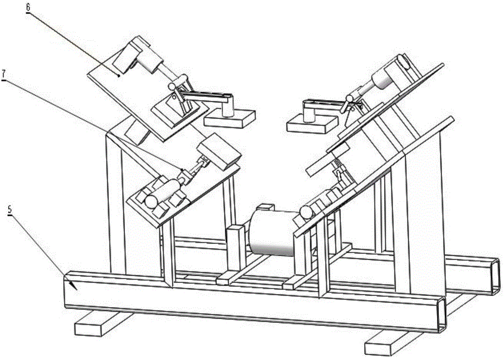
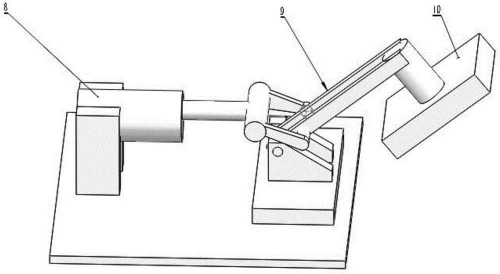
[0019] Depend on figure 2 , image 3 , Figure 4 It can be seen that the broken belt arresting device of the belt conveyor comprises a frame (5), an upper arresting mechanism (6) and a lower arresting mechanism (7). The upper catch...


PUM


Abstract

The invention discloses a belt breakage catching device of a belt type conveyor. The belt breakage catching device comprises a control host, a belt breakage detection device and multiple catching substations. The control host and the catching substations are connected through communication lines. The control host is further connected with the belt breakage detection device. The catching substations are evenly arranged on the belt type conveyor at equal intervals. When a belt breakage accident happens, a sensor detects a belt breakage signal, the control host issues a catching instruction to each catching substation, control units are connected with electromagnetic valves after the catching substations receive the instruction, air enters air cylinders through air inlets, piston rods of the air cylinders stretch out, lower gate segment air cylinder piston rods drive sliding blocks to move forwards along guide rails, guide rods connected to knuckle bearings are pushed, and then the sliding blocks in the perpendicular direction are pushed to move upwards to be in fit with upper gate segments of upper catching mechanisms. According to the belt breakage catching device, a belt breakage catching device of a coal mine belt type conveyor is unreasonable in solved, the structure is simple, testing and overhaul are convenient, and the equipment manufacturing cost is low.

Description

technical field [0001] The invention relates to a broken belt arresting device of a belt conveyor, which belongs to the technical field of conveyor belt protection. It is especially suitable for broken belt protection of inclined belt conveyors used in metallurgical mines, coal mines, port terminals and power plants. Background technique [0002] Belt conveyors are used in many fields. When a broken belt occurs on a belt conveyor, especially an inclined, long-belt, or large-capacity belt conveyor, it will cause long-term production stoppages and huge economic losses, even machine crashes. , the consequences are extremely serious. [0003] At present, there are many kinds of broken belt arresting devices for belt conveyors, but there are still the following problems: when catching the brake belt, some use line contact, the braking force is small, the braking force is concentrated, and it is easy to damage the belt; Contact, the arresting force reaches a large moment, and it...

Claims


Application Information

Patent Timeline
Patent Type & Authority Applications(China)
IPC IPC(8): B65G43/06
CPCB65G43/06B65G2203/0275
Inventor 付胜易高胜
Owner BEIJING UNIV OF TECH
Why Eureka
Try Eureka