Near/far field broadband mixed source far field source direction finding method based on amplitude-phase error array
An amplitude and phase error, array technology, applied in the field of far-field source direction finding, can solve the problem of inaccurate direction of arrival estimation, and achieve the effects of saving calculation time, high estimation accuracy, and improving efficiency
- Summary
- Abstract
- Description
- Claims
- Application Information
AI Technical Summary
Problems solved by technology
Method used
Image
Examples
specific Embodiment approach 1
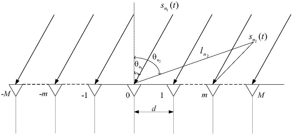
[0016] Specific implementation mode one: combine figure 1 To illustrate this embodiment, the specific process of the far-near-field broadband hybrid source mid-far field source direction finding method based on the amplitude and phase error array of this embodiment is as follows:
[0017] Step 1. Build an ideal source model;
[0018] Step 2, constructing the source model under the array amplitude and phase error according to the source model under ideal conditions;
[0019] Step 3: Calculate the estimated value of the direction of arrival of the far-field signal source according to the signal source model under the array amplitude and phase error.
specific Embodiment approach 2
[0020] Specific implementation mode two: the difference between this implementation mode and specific implementation mode one is: the source model under ideal conditions is constructed in the step one; the specific process is:
[0021] Such as figure 1 shown, assuming N 1 far-field chirp broadband sources and N 2 near-field chirp broadband source At the same time, it arrives on a uniform linear array composed of 2M+1 omnidirectional array elements, and the arrival angle is θ. where N=N 1 +N 2 , N is the total number of information sources; N, N 1 , N 2 The value is a positive integer, and the value of M is a positive integer; the value of θ is -90°~+90°;
[0022] Assuming that the number of far and near field sources is known, the sources are not correlated with each other and the power reaching the array is equal, the 0th array element is used as the phase reference point, and the near field sources The distance from the phase reference point is The array elem...
specific Embodiment approach 3
[0051] Specific implementation mode three: this implementation mode is different from specific implementation mode one or two in that: in said step two, construct the signal source model under the array amplitude and phase error according to the signal source model under ideal conditions; the specific process is:
[0052] When there is an array amplitude and phase error, W(f i ) means the frequency point f i The array amplitude and phase error matrix on is expressed as:
[0053] W(f i ) = diag([W -M (f i ),…,W -m (f i ),…,1,…,W m (f i ),…,W M (f i )] T ) (12)
[0054] in
[0055]
[0056] In the formula, diag means to take the diagonal matrix of the vector, ρ m (f i ), Respectively, the source frequency is f i When , the amplitude gain and phase deviation of the mth array element relative to the 0th array element has nothing to do with the arrival direction of the signal source, so when there is an array amplitude and phase error, the nth signal source is a...
PUM
 Abstract
Description
Claims
Application Information
 - R&D
- Intellectual Property
- Life Sciences
- Materials
- Tech Scout
- Unparalleled Data Quality
- Higher Quality Content
- 60% Fewer Hallucinations
Browse by: Latest US Patents, China's latest patents, Technical Efficacy Thesaurus, Application Domain, Technology Topic, Popular Technical Reports.
© 2025 PatSnap. All rights reserved.Legal|Privacy policy|Modern Slavery Act Transparency Statement|Sitemap|About US| Contact US: help@patsnap.com


