
Spring supporting rod

A technology of support rods and spring barrels, applied in the direction of springs, springs/shock absorbers, shock absorbers, etc., can solve problems such as seal ring failure, and achieve the effect of avoiding bump damage

Inactive Publication Date: 2017-04-05
CHINA AVIATION OPTICAL-ELECTRICAL TECH CO LTD
View PDF7 Cites 4 Cited by
  • Summary
  • Abstract
  • Description
  • Claims
  • Application Information

AI Technical Summary

Problems solved by technology

[0003] The invention provides a spring support rod to solve the problem in the prior art that the sealing ring of the gas spring support rod is easily affected by the environment and fails

Method used


Image

  • Spring supporting rod
  • Spring supporting rod

Examples


Embodiment Construction

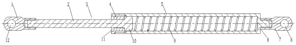
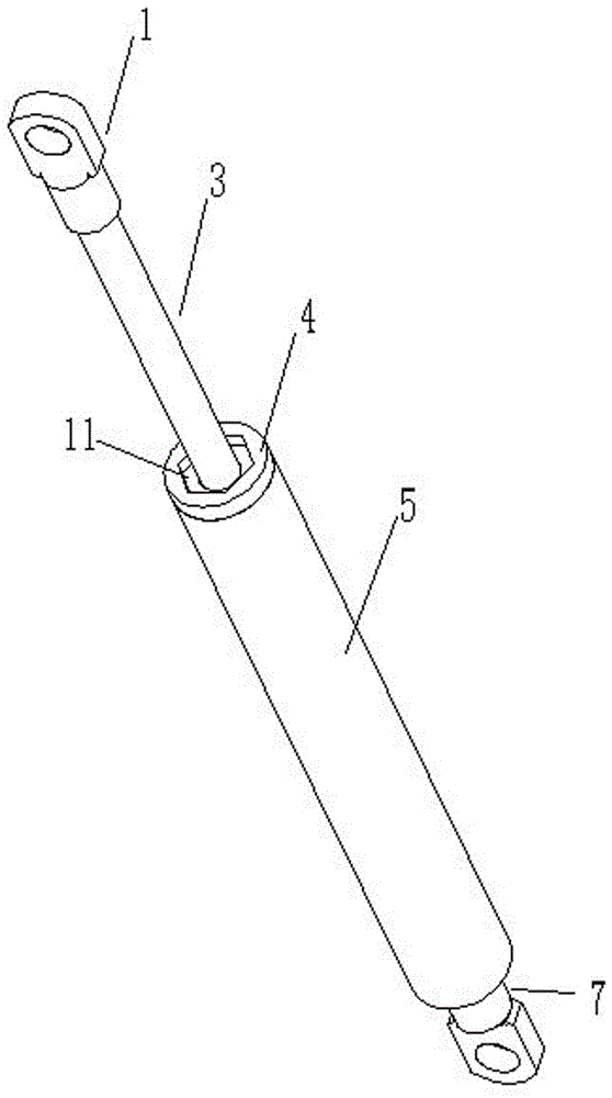
[0016] Examples of spring struts are Figure 1~2 As shown: the spring support rod includes a spring tube and a support rod 3, the spring tube includes a cylinder body 5 whose axis extends in the front-to-back direction, the front end of the inner hole of the cylinder body 5 is a threaded section, and a nut 4 is screwed on the threaded section, An inner square hole structure 11 for torque input is arranged coaxially on the front end face of the nut. The rear end of the cylinder body 5 is integrally provided with a cylinder bottom 8, on which the spring cylinder connecting ear 7 is screw-mounted, the spring cylinder connecting ear 7 is provided with a spring cylinder hinge hole 6, the spring cylinder connecting ear 7 and the spring cylinder hinge hole 6 constitutes the connection structure for connecting the spring tube to the spring tube on the first component. The support rod is a stepped shaft structure, and the support rod includes a large-diameter section 10 assembled in t...


PUM


Abstract

The invention relates to a spring supporting rod which comprises a spring barrel. The spring barrel comprises a barrel body with the axis extending in the front-and-back direction. A supporting rod body is assembled on the spring barrel in a guide movement manner in the front-and-back direction. A supporting rod limiting structure used for being in limiting fit with the supporting rod body so as to limit the forward movement limit of the supporting rod body is arranged on the barrel body. A supporting spring applying forward acting force to the supporting rod body is arranged between the supporting rod body and the spring barrel. The supporting spring is located in the barrel body. A spring barrel connecting structure used for connecting the spring barrel to a first component is arranged on the spring barrel. A supporting rod connecting structure used for connecting the supporting rod body to a second component is arranged on the supporting rod body. The spring supporting rod solves the problem that in the prior art, a sealing ring of an air spring supporting rod is prone to being influenced by the environment to fail.

Description

technical field [0001] The invention relates to a spring support rod. Background technique [0002] The gas spring support rod is a relatively common spring support rod. The gas spring support rod includes a sealing cylinder and a piston rod. The sealing cylinder is provided with a sealing cylinder connection structure for connecting the sealing cylinder to the first part. The piston rod includes a rod body And the piston that is assembled through the sealing ring and the sealing cylinder for sealing and guiding. The rod body is provided with a piston rod connection structure for connecting the piston rod to the second part. The piston separates the sealing cylinder into a rod chamber and a rodless chamber. The sealing cylinder The rodless cavity is filled with compressed gas. When in use, the piston rod moves to compress the compressed gas in the rodless cavity, so that the pressure on both sides of the piston is different, thereby providing an elastic support force for th...

Claims


Application Information

Patent Timeline
IPC IPC(8): A47C19/02F16F9/02F16F9/32F16F9/54
CPCA47C19/02F16F9/0218F16F9/3207F16F9/54
Inventor 李国胜胡晓松张洋
Owner CHINA AVIATION OPTICAL-ELECTRICAL TECH CO LTD
Features
  • Generate Ideas
  • Intellectual Property
  • Life Sciences
  • Materials
  • Tech Scout
  • Unparalleled Data Quality
  • Higher Quality Content
  • 60% Fewer Hallucinations
Learn More