Inner Rotor Motor, Rotor of Inner Rotor Motor and Selection Method of Its Size

A technology for inner rotor motors and rotors, applied in the manufacture of stator/rotor bodies, magnetic circuit rotating parts, magnetic circuit shape/style/structure, etc., can solve problems such as volume reduction, vibration, deformation, etc.

Active Publication Date: 2019-02-22
SUNONWEALTH ELECTRIC MACHINE IND
View PDF8 Cites 0 Cited by
  • Summary
  • Abstract
  • Description
  • Claims
  • Application Information

AI Technical Summary

Problems solved by technology

[0003] However, it is difficult to select the size of the permanent magnet 93 when designing the rotor 9.
Specifically, if the size of the permanent magnets 93 is too small, the magnetic flux between the permanent magnets 93 will be too low, resulting in insufficient magnetic strength of the magnetic poles of the rotor 9, thus affecting the operation of the inner rotor motor using the rotor 9 Efficiency; relatively, if the size of the permanent magnet 93 is too large, it will inevitably lead to the reduction of the volume of the magnetic pole part 922, causing the overall structural strength of the iron core 92 to be insufficient, and noise will be generated during the rotation of the rotor 9 , vibration or even deformation
[0004] In view of this, it is urgent to provide a further improved inner rotor motor, the rotor of the inner rotor motor and its size selection method, so as to solve the above-mentioned problem that the rotor 9 of the existing inner rotor motor is difficult to design

Method used


Image

  • Inner Rotor Motor, Rotor of Inner Rotor Motor and Selection Method of Its Size
  • Inner Rotor Motor, Rotor of Inner Rotor Motor and Selection Method of Its Size
  • Inner Rotor Motor, Rotor of Inner Rotor Motor and Selection Method of Its Size

Examples


Embodiment Construction

[0048] In order to make the above and other objects, features and advantages of the present invention more comprehensible, preferred embodiments of the present invention will be described in detail below together with the accompanying drawings.

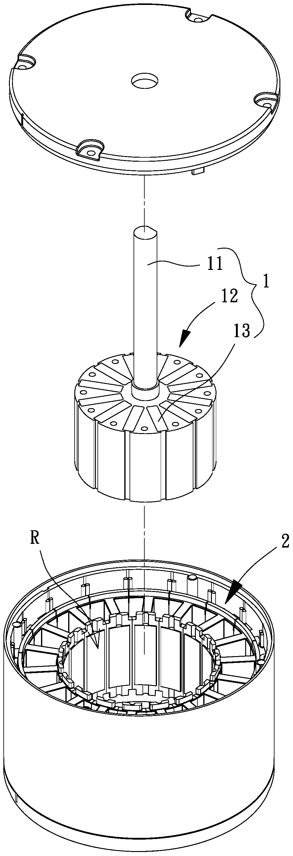
[0049] Please refer to figure 2 Shown is an inner rotor motor according to an embodiment of the present invention, which includes a rotor 1 and a stator 2 , and the rotor 1 is rotatably combined with the stator 2 .

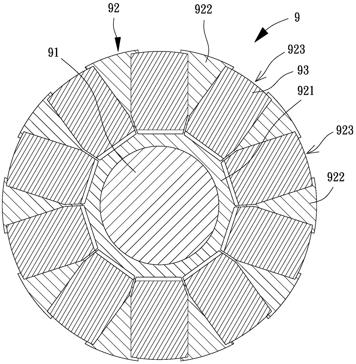
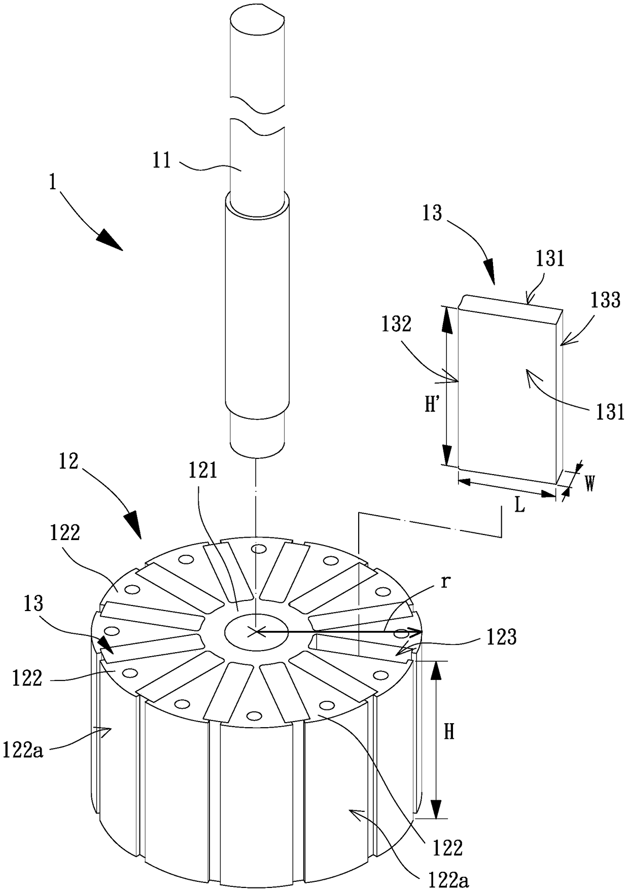
[0050] Please refer to image 3 As shown, it is an enlarged and exploded schematic view of the rotor 1 . The rotor 1 includes a rotating shaft 11 , an iron core 12 and several permanent magnets 13 . The iron core 12 is combined with the rotating shaft 11 , and the permanent magnet 13 is disposed on the iron core 12 . Furthermore, the stator 2 surrounds and forms an accommodating space R, the iron core 12 and the permanent magnet 13 can be disposed in the accommodating space R, and the rotating shaft 11 forms a rotatabl...


PUM


Abstract

The present invention relates to an inner rotor motor, a rotor of the inner rotor motor and a size selection method thereof. The rotor comprises a rotating shaft, an iron core and a plurality of permanent magnets. The iron core comprises a magnet yoke part and a plurality of magnetic pole parts. The magnet yoke part is combined with the periphery of the above rotating shaft, the plurality of magnetic pole parts are arranged at the periphery of the magnet yoke part along a circumferential direction, and an accommodating groove is formed between two adjacent magnetic pole parts in the circumferential direction. The permanent magnets are arranged in the accommodating grooves respectively, wherein the magnetic pole end faces are formed at the sides of the magnetic pole parts far away from the rotating shaft, and the magnetic pole end faces of the magnetic pole parts extend in the circumferential direction to form a peripheral surface having an area. Each above permanent magnet comprises two first surfaces facing the magnetic pole parts, a second surface facing the above magnet yoke part and a third surface far away from the magnet yoke part, the two first surfaces, the second surface and the third surface have an area sum, and the ratio of the area sum and the area of the peripheral surface is between 0.15 and 0.36.

Description

technical field [0001] The invention relates to an inner rotor motor, a rotor of the inner rotor motor and a method for selecting the size thereof, in particular to a rotor including an iron core, an inner rotor motor provided with the rotor, and a method for selecting the size of the rotor. Background technique [0002] Please refer to figure 1 Shown is a rotor 9 of an existing inner rotor motor, which includes a rotating shaft 91 , an iron core 92 and several permanent magnets 93 . The iron core 92 includes a tubular connecting portion 921, the tubular connecting portion 921 is combined with the outer periphery of the rotating shaft 91, and the tubular connecting portion 921 is connected with several magnetic pole portions 922, the number of the magnetic pole portions 922, the number of the permanent magnets 93 The number corresponds to the number of magnetic poles of the rotor 9 . Wherein, the iron core 92 includes several magnet accommodation air gaps 923, the magnet a...

Claims


Application Information

Patent Timeline
Patent Type & Authority Patents(China)
IPC IPC(8): H02K1/27H02K15/03
Inventor 洪银树王启民陈冠铭
Owner SUNONWEALTH ELECTRIC MACHINE IND
Why Eureka
Try Eureka