
Suspension rail type slurry extracting and levelling machine

A technology of leveling machine and suspension rail, which is applied to bridge parts, erecting/assembling bridges, bridges, etc., can solve the problems of flatness and waterproof performance, difficult to guarantee flatness, poor integrity of concrete, etc., to improve construction quality, Avoid secondary seams and ensure the effect of stiffness

Inactive Publication Date: 2017-04-19
张守胜
View PDF5 Cites 8 Cited by
  • Summary
  • Abstract
  • Description
  • Claims
  • Application Information

AI Technical Summary

Problems solved by technology

The traditional leveling layer construction method often uses artificial rollers or mechanical three-roller shafts or planetary frame leveling machines to level and lift the concrete surface after concrete paving, and the equipment is laid along the track on the top of the beam. Mobile, this method needs to plant steel bars on the top of the beam in advance due to the existing technology, which requires a large amount of consumables and high costs, and the track needs to be installed in advance. poor, inefficient
[0003] Furthermore, with traditional construction equipment and methods, because the track is laid on the top of the beam slab, and due to the mutual interference between the guardrail and the track, it is often necessary to adopt a secondary construction method, that is, to construct an auxiliary belt with a width of 0.5m on both sides first. After the construction of the auxiliary belt is completed, pave the track on it; or erect the track on both sides first, pour the concrete in the middle, and then pour the post-casting belt on both sides for the second time. Obviously, the longitudinal construction joints on both sides must be added, resulting in concrete The integrity is poor, and the flatness and waterproof performance are affected; but there are also one-time pouring, that is, the concrete on both sides of the track is vibrated with a vibrator, which is manually smoothed, and due to the influence of the overhead track, the construction efficiency Low, flatness is difficult to guarantee

Method used


Image

  • Suspension rail type slurry extracting and levelling machine
  • Suspension rail type slurry extracting and levelling machine
  • Suspension rail type slurry extracting and levelling machine

Examples


Embodiment 1

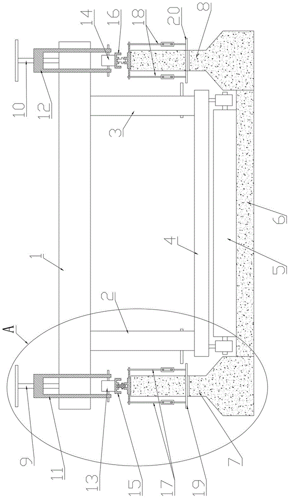
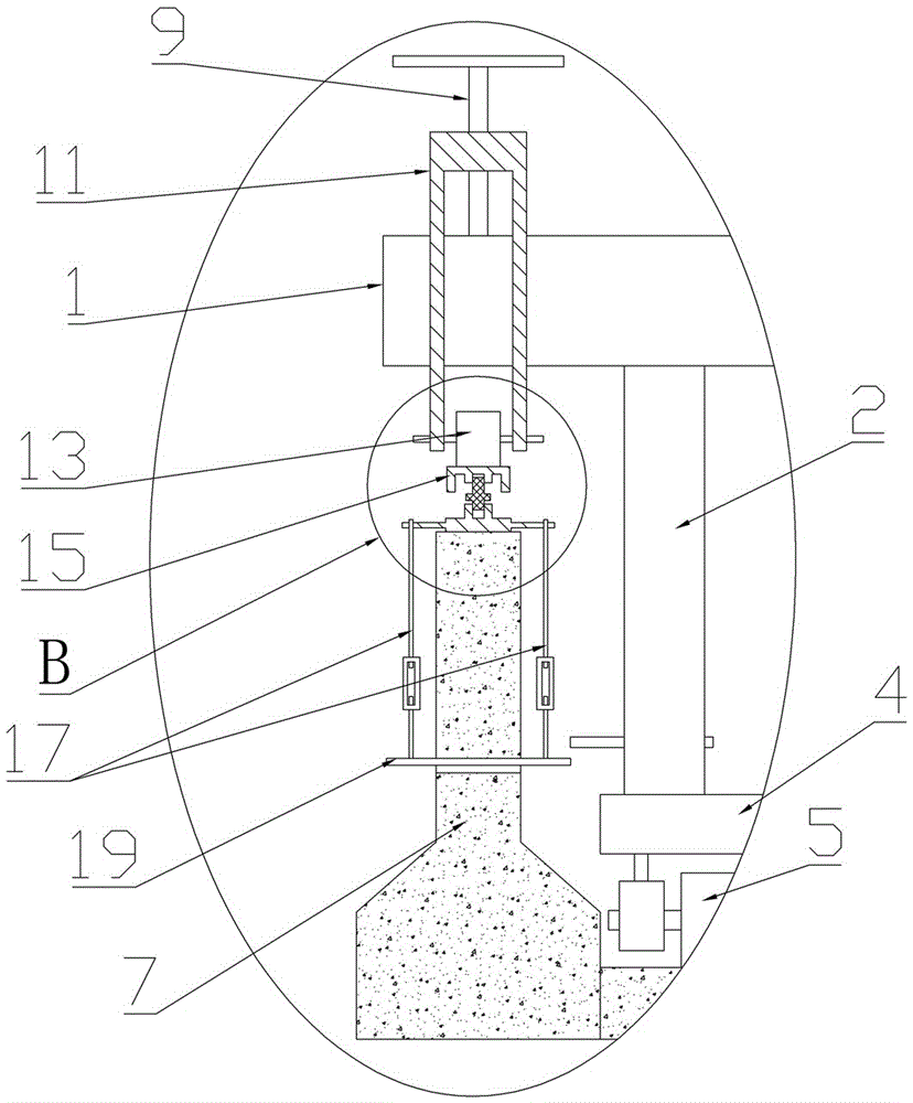
[0026] Embodiment 1: a kind of suspension rail type pulp leveling machine, see Figure 1 to Figure 7 It comprises two parallel tracks 15,16 laid on the anti-collision guardrails 7,8 on both sides of the bridge plate 6, a suspension mechanism that is arranged on the two tracks 15,16 and can slide on the tracks 15,16, Further, a fastening and leveling mechanism for fixing and leveling the rails 15 and 16 is also included.

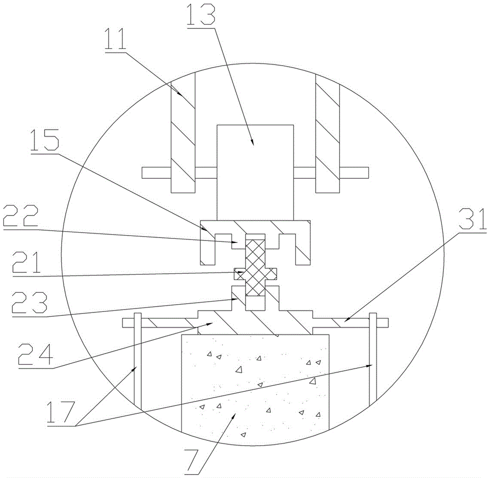
[0027] In this embodiment, the fastening and leveling mechanism includes a fixing plate 24 arranged on the anti-collision barriers 7 and 8, a lower support pipe 23 arranged on the fixing plate 24 and internally provided with internal threads, On the lower surface of the rails 15, 16 that are arranged opposite to the lower support pipe 23, an upper support pipe 22 that is also provided with an internal thread is also provided inside, and an adjustment screw 21 is also included, and the upper end and the lower end of the adjustment screw 21 The screw threads o...


PUM


Abstract

The invention provides a suspension rail type slurry extracting and levelling machine, being able to improve the flatness of a levelling layer, reduce the longitudinal consumables and improving the efficiency. The suspension rail type slurry extracting and levelling machine includes two parallel rails, a suspension mechanism, a base plate, and roll shafts, wherein the rails are paved on crashproof guardrails at two sides of a bridge plate; the suspension mechanism is arranged on the two rails, and can slide on the rails; the base plate is arranged below the suspension mechanism, and is connected with the suspension mechanism through connecting pieces; two ends of each roll shaft are each correspondingly provided with a bearing pedestal; two bearing pedestals on two ends of each roll shaft are respectively provided with a first height adjusting mechanism for adjusting the height of the end parts of the roll shaft; and the two bearing pedestals are respectively connected with the base plate through the first height adjusting mechanisms.

Description

technical field [0001] The invention relates to the technical field of civil engineering, in particular to a suspension rail type pulp leveling machine. Background technique [0002] In order to strengthen the overall stress effect between the beams and slabs and adjust the flatness of the top surface of the bridge after the beams and slabs of the highway bridge are installed, a 6-10cm thick leveling layer is generally provided on the top of the beams and slabs. The traditional leveling layer construction method often uses artificial rollers or mechanical three-roller shafts or planetary frame leveling machines to level and lift the concrete surface after concrete paving, and the equipment is laid along the track on the top of the beam. Mobile, this method needs to plant steel bars on the top of the beam in advance due to the existing technology, which requires a large amount of consumables and high costs, and the track needs to be installed in advance. Poor and inefficient...

Claims


Application Information

Patent Timeline
IPC IPC(8): E01D21/00E01D19/08
CPCE01D21/00E01D19/083
Inventor 张守胜
Owner 张守胜
Learn More