Arc-shaped gas-water separator

A gas-water separator, arc-shaped technology, applied in degassed water/sewage treatment, water/sewage treatment, chemical instruments and methods, etc., can solve the difficulties of vertical drilling, insufficient space for electric drill operation, and guarantee of gas-water separation effect In order to achieve the effects of fast and thorough air bubble escape, low-cost operation of sewage treatment, and remarkable effect of gas-water separation

Pending Publication Date: 2021-05-04
WUHAN PURGELON ENVIRONMENTAL ENG TECH
View PDF1 Cites 0 Cited by
  • Summary
  • Abstract
  • Description
  • Claims
  • Application Information

AI Technical Summary

Problems solved by technology

However, in addition to occupying land, the traditional method also consumes two parts of the water head from the aeration tank to the air-water separation box/room and the air-water separation box/room to the secondary sedimentation tank, which makes the water head loss in the process larger, which is not conducive to energy saving operation, and because the surface of the aeration tank and the secondary sedimentation tank will inevitably have a large height difference, which is not conducive to the layout of the process flow and the integrated construction of civil engineering
[0003] my country's patent "Horizontal Slit Type Gas-Water Separator" (notification number CN 103395853 A, announcement date 2013.11.20), the equipment is composed of ascending deflector sloping plate, vertical stabilizing plate, oblique deflecting silt plate, et

Method used


Image

  • Arc-shaped gas-water separator
  • Arc-shaped gas-water separator
  • Arc-shaped gas-water separator

Examples


Embodiment 1

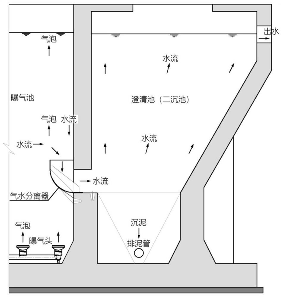
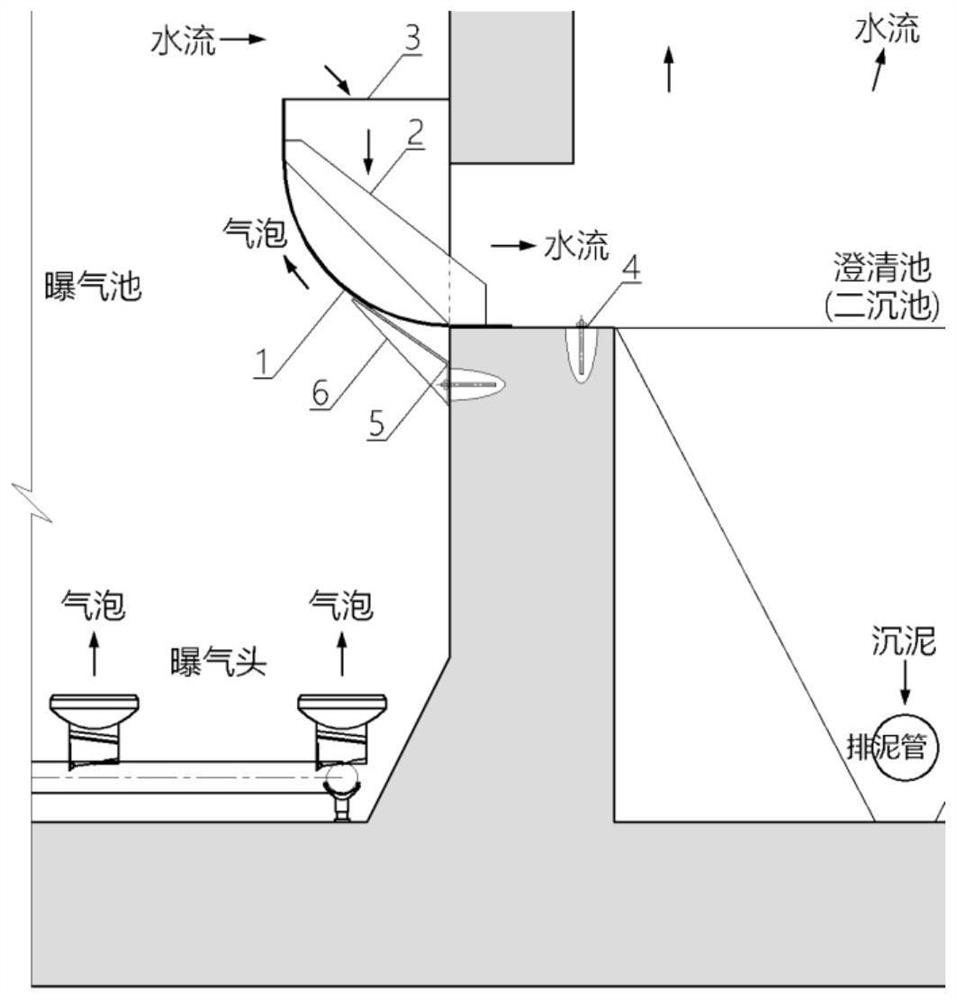
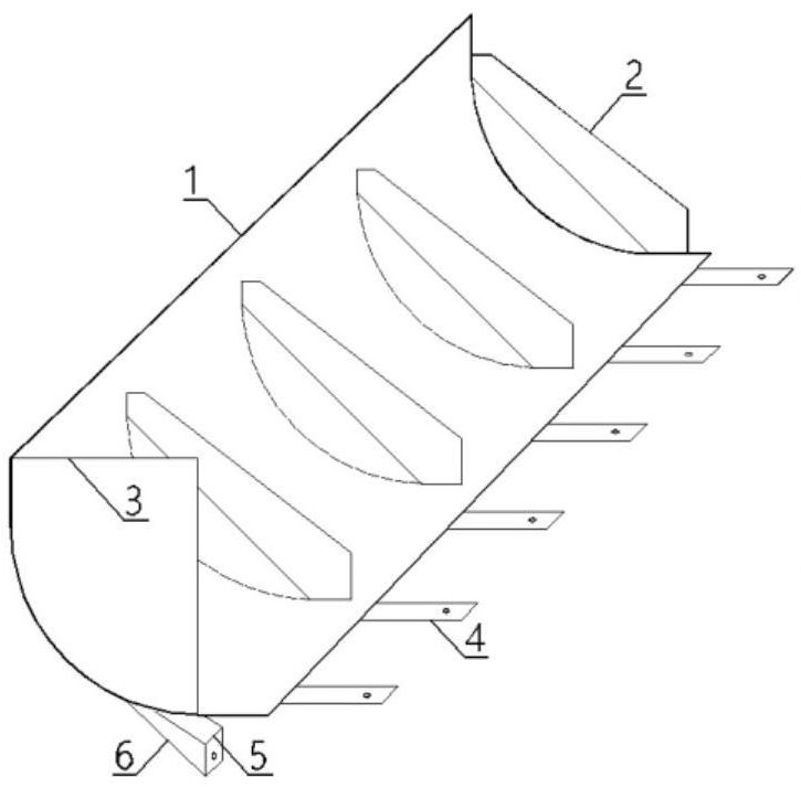
[0033] Please refer to the attached figure 1 , figure 2 , image 3 At the same time, in combination with a sewage treatment project in Nanyang City, Henan Province, an arc-shaped gas-water separator of the present invention is used as an embodiment to further describe the present invention in detail. Therefore, this embodiment provides a practical technical solution that has been successfully used.

[0034] It should be emphasized here that the description of the specific technical solutions of the embodiments is used to help understand the essence and intent of the present invention, and does not constitute a limitation of the present invention. In addition, in the following descriptions, descriptions of known technologies and familiar structures (such as lap welding, segmental manufacturing for vehicle transportation and bolting or welding on site, etc.) are omitted in order to avoid unnecessary confuse the concept of the present invention.

[0035] The sewage treatment...

Embodiment 2

[0051] Taking a township sewage treatment project in Qianjiang City, Hubei Province as an example of using an arc-shaped gas-water separator of the present invention, the present invention will be further described in detail. Therefore, this embodiment provides another practical and feasible technical solution that has been successfully used.

[0052] The sewage treatment scale of this embodiment is 1600m 3 / d, in order to facilitate non-stop production during pool or equipment maintenance, the design is divided into 2 grids of 800m each 3 / d integrated aeration and sedimentation tank, figure 1 Shows a single cell 800m 3 / d The schematic diagram of the rear end of the integrated tank, that is, the schematic diagram of the on-site assembly and use of the arc-shaped gas-water separator in this embodiment, the effective water depth of the aeration tank is 4.30m, and 4 arc-shaped gas-water separators are installed on 2 At each water-passing hole with a horizontal length of 4.02...


PUM


Abstract

The invention provides an arc-shaped gas-water separator which is characterized by comprising an arc-shaped plate, a plurality of reinforcing and supporting vertical ribs located in the inner side of the arc-shaped plate, a vertical baffle arranged at one end of the arc-shaped plate, a plurality of horizontal fixing bottom plates horizontally extending and lapped on the lower side of the arc-shaped plate, a lower fixing L-shaped folded plate welded to the bottom of the arc-shaped plate and the like. The gas-water separator is arranged between a sewage aeration tank and a secondary sedimentation tank, the outer side of the arc-shaped plate faces the aeration tank, the inner side of the arc-shaped plate faces a through-wall hole communicated with the aeration tank and the secondary sedimentation tank, and a flow channel formed by the arc-shaped plate and the through-wall hole is an equal-diameter flow channel. The gas-water separator is simple in structure, smooth, free of blockage and small in head loss, and compared with an existing gas-water separation device, the gas-water separator has the advantages of being energy-saving, free of faults, low in manufacturing cost, small in occupied area, good in gas-water separation effect and the like.

Description

technical field [0001] The invention belongs to the field of gas-water separation of sewage aeration biochemical treatment technology, and specifically relates to an arc-shaped aeration system that can realize rapid, convenient and smooth separation of air bubbles and activated sludge mixed liquid before the gas-liquid-solid three-phase mixed liquid enters the secondary settling tank. water separator. Background technique [0002] In the field of sewage biochemical treatment technology, when the aeration tank and the secondary settling tank are jointly built (shared pool wall), if the mixed liquid in the aeration tank directly enters the secondary settling tank, it will bring a bad problem-the mixed liquid The medium air bubbles enter the secondary settling tank with the water flow, which will disturb the sedimentation layer of activated sludge and seriously affect the effluent water quality of the secondary settling tank. In the past, in order to eliminate the air bubbles ...

Claims


Application Information

Patent Timeline
IPC IPC(8): C02F1/20C02F3/12
CPCC02F1/20C02F3/12C02F3/1215C02F3/1236C02F2201/002C02F2203/006Y02W10/10
Inventor 刘贤斌李路周安妮
Owner WUHAN PURGELON ENVIRONMENTAL ENG TECH
Why Eureka
Try Eureka