Variable-height cable-truss bridge reinforcing structure system

A technology for strengthening structures and changing heights, which is applied in bridge reinforcement, erection/assembly of bridges, bridges, etc. It can solve the problems of cumbersome construction, reduce the peak bending moment of bridge slabs and mid-span section deflection, and difficulty, and achieve remarkable reinforcement effects , reduce the peak bending moment and mid-span section deflection, and shorten the construction period

Active Publication Date: 2017-04-19
ZHEJIANG UNIV
View PDF6 Cites 9 Cited by
  • Summary
  • Abstract
  • Description
  • Claims
  • Application Information

AI Technical Summary

Problems solved by technology

[0003] In order to overcome the cumbersome and difficult construction of the existing bridge temporary reinforcement technology and the shortcomings of the reinforcement effect being restricted by factors such as bridge type and environment, the present invention provides a variable-height cable-truss bridge reinforcement structure system, which is independent of the main structure of the bridge. The reinforcement can be completed without affecting the normal traffic function of the bridge. The structural form of the vertical web bar with variable height can make the jacking force acting on the bridge slab more uniform, greatly reduce the peak bending moment of the bridge slab and the deflection of the mid-span section, and improve The internal force distribution of the bridge slab can effectively improve the structural bearing capacity and stiffness

Method used


Image

  • Variable-height cable-truss bridge reinforcing structure system
  • Variable-height cable-truss bridge reinforcing structure system
  • Variable-height cable-truss bridge reinforcing structure system

Examples


Embodiment approach

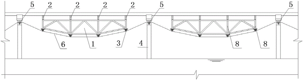
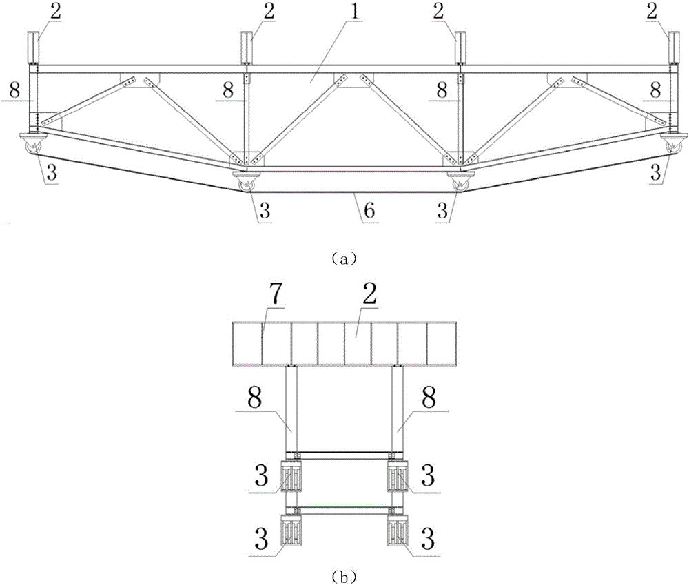
[0021] see figure 1 and figure 2 , the embodiments of the present invention include:

[0022] exist figure 1 In the middle, the variable-height cable-truss bridge reinforcement structure system is arranged under the bridge deck, and the tops of the two trusses 1 are connected by distribution beams 2, and the distribution beam 2 is tightly topped on the lower surface of the bridge deck, and the force transmission pulleys are fixed at the four corners of the lower part of the truss 1 3. The diverting pulley 5 is fixed on the upper part of the piers 4 on both sides, and the prestressed steel strand 6 passes through each force transmission pulley 3 and the diverting pulley 5 in turn to combine the truss 1 and the piers 4 on both sides to jointly bear the force. Since the distribution beam 2 in this structural system is subjected to relatively large concentrated loads, it is usually necessary to take structural measures to add distribution beam stiffeners 7 to this part of the s...


PUM


Abstract

The invention discloses a variable-height cable-truss bridge reinforcing structure system. The system comprises five parts including a prestress wire, a truss, a distributing beam, steering sliding wheels and a force transmission sliding wheel; the steering sliding wheels are fixed to the upper portion of a bridge pier, the inversed force transmission sliding wheel is fixed to the bottom of the truss, and the distributing beam is placed on the top; and the prestress wire sequentially penetrates the steering sliding wheels and the force transmission sliding wheel for connecting the fixed end and the stretching end on the two sides of an overall bridge, and therefore the distributing beam abuts against the lower surface of a top bridge plate. the prestress wire form upward resultant force at the bottom of the truss, and the resultant force is transmitted by the truss to the bridge face plate to form jacking force. The lengths of vertical web members of the truss are in bilateral symmetry, the vertical web members on the outmost sides are shortest, and the best reinforcing effect is achieved. By means of the above manner, the dead load of the bridge plate can be partially offset, the bearing capacity and the rigidity of the structure are effectively improved, and the aim of reinforcing the bridge is achieved.

Description

technical field [0001] The invention relates to the field of bridge reinforcement engineering, in particular to a temporary reinforcement structure system capable of improving the overload capacity of long-span bridges and realizing the purpose of passing large transport vehicles. Background technique [0002] At present, the known temporary reinforcement technologies for overweight vehicles crossing bridges mainly include the following: one is to adopt the method of pasting carbon fiber reinforcement, and use epoxy resin or special glue to directly paste carbon fiber cloth or plates on the surface of concrete components, so that The components form a stressed whole, but this method needs to clear and level the surface concrete, which will cause great damage to the bridge deck and affect the normal traffic of the bridge during construction; the second is to adopt the steel column support reinforcement method, and place cast-in-place piles on the outside of the river bridge de...

Claims


Application Information

Patent Timeline
Patent Type & Authority Applications(China)
IPC IPC(8): E01D22/00
CPCE01D22/00
Inventor 罗尧治陈勤李洋沈雁彬许贤
Owner ZHEJIANG UNIV
Why Eureka
Try Eureka