
Plane with nose-up pitching moment

A nose-up moment, aircraft technology, applied in the field of aviation aircraft, can solve problems such as weak climbing ability, slow take-off of aircraft, poor anti-interference ability, etc., to achieve the effect of enhancing anti-interference ability, good maneuverability and stability, and ensuring normal flight

Pending Publication Date: 2017-05-31
丰翼科技(深圳)有限公司
View PDF4 Cites 0 Cited by
  • Summary
  • Abstract
  • Description
  • Claims
  • Application Information

AI Technical Summary

Problems solved by technology

However, in practical applications, the horizontal stabilizer does not consider the influence of the fuselage in its design, which greatly reduces its effect
Under normal circumstances, the horizontal tail is installed at the tail of the fuselage. Due to the influence of the flow field of the fuselage, the lift generated by the horizontal tail will often be weakened, which will produce a different effect than expected, resulting in slow take-off and weak climbing ability of the aircraft. Poor anti-jamming capability, which is not conducive to controlling the flight attitude of the aircraft and improving flight stability

Method used


Image

  • Plane with nose-up pitching moment
  • Plane with nose-up pitching moment

Examples


Embodiment 1

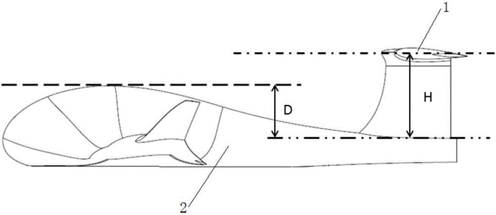
[0025] Such as figure 1 Shown, a kind of aircraft of head-up moment comprises fuselage 2 and empennage, and described empennage comprises vertical empennage and horizontal empennage 1, and vertical empennage is installed on the rear portion of described fuselage 2, and horizontal empennage 1 is installed on the top of vertical empennage , forming a T-shaped tail, a raised portion is set on the top surface of the front of the fuselage 2, and the smooth transition between the raised portion and the rear of the fuselage 2 makes the top surface of the fuselage 2 form a streamlined surface.

[0026] The horizontal stabilizer 1 is a symmetrical airfoil, and the lowest point of the top surface of the fuselage 2 is located at the tail end of the fuselage 2 . The lowest point of the top surface of the fuselage 2 is located at the rear end of the fuselage 2, so that the flow of the air on the surface of the aircraft is laminar, avoiding turbulent flow, the aircraft suffers the least res...

Embodiment 2

[0032] The features identical to those of the first embodiment will not be described in detail. The different features of the first embodiment are: the height difference between the highest point and the lowest point of the top surface of the fuselage 2 is D, and the upper surface of the horizontal stabilizer 1 is The height difference from the lowest point on the top surface of the fuselage 2 is H, and D=1.0H.

Embodiment 3

[0034] The features identical to those of the first embodiment will not be described in detail. The different features of the first embodiment are: the height difference between the highest point and the lowest point of the top surface of the fuselage 2 is D, and the upper surface of the horizontal stabilizer 1 is The height difference from the lowest point on the top surface of the fuselage 2 is H, and D=1.3H.

[0035] In the present invention, the relationship between the height difference D between the highest point and the lowest point of the fuselage 2 top surface and the height difference H between the horizontal stabilizer 1 upper surface and the lowest point of the fuselage 2 top surface is not limited to the embodiment Among the several values ​​mentioned above, D can also take other values ​​greater than 0.3H and less than 2H.


PUM


Abstract

The invention discloses a plane with nose-up pitching moment and relates to the technical field of aviation aircrafts. The plane structurally comprises a plane body and an empennage, wherein the empennage comprises a vertical empennage and a horizontal empennage; the vertical empennage is arranged at the rear part of the plane body; the horizontal empennage is arranged at the top end of the vertical empennage to form a T-shaped empennage; a bulge part is arranged on the top surface of the front part of the plane body; and smooth transition is adopted between the bulge part and the rear part of the plane body, so that the top surface of the plane body forms a streamlined surface. The height difference between the highest point and the lowest point of the top surface of the plane body is D, and the height difference between the lowest points of the upper surface of the horizontal empennage and the top surface of the plane body is H, wherein D is more than 0.3H and less than 2H. The plane disclosed by the invention has the advantages that the top surface of the front part of the plane body is bulged, so that the flow field generates deflection; and the flow fields of the upper surface and lower surface of the horizontal empennage are not symmetrical, and at the time, the nose-up pitching moment is generated for the plane body, so that the stability of the plane in the flight process is guaranteed.

Description

technical field [0001] The invention relates to the technical field of aviation aircraft, in particular to an aircraft with nose-up moment. Background technique [0002] Horizontal stabilizer, referred to as the horizontal tail, is installed at the rear of the fuselage and is mainly used to maintain the stability of the aircraft in flight and control the flight attitude of the aircraft. However, in practical applications, the horizontal stabilizer does not take into account the influence of the fuselage in the design, so that its effect is greatly reduced. Under normal circumstances, the horizontal tail is installed at the tail of the fuselage. Due to the influence of the flow field of the fuselage, the lift generated by the horizontal tail will often be weakened, which will produce a different effect than expected, resulting in slow take-off and weak climbing ability of the aircraft. The anti-jamming ability is poor, which is not conducive to controlling the flight attitud...

Claims


Application Information

Patent Timeline
Patent Type & Authority Applications(China)
IPC IPC(8): B64C5/02B64C5/06B64C1/00
CPCB64C1/0009B64C5/02B64C5/06
Inventor 李晓亮张彬华
Owner 丰翼科技(深圳)有限公司
Learn More