
External clutch device with good anti-theft property and used for intelligent lock

The technology of a clutch device and an intelligent lock, which is applied to the shell of the lock, the non-mechanical transmission-operated lock, the building lock, etc., can solve the problems of low anti-theft performance, increase the thickness of the lock panel, and hidden safety hazards, and achieve better clutch effect. Enhance anti-theft performance and accurate alignment

Active Publication Date: 2017-04-19
廖伟新
View PDF9 Cites 7 Cited by
  • Summary
  • Abstract
  • Description
  • Claims
  • Application Information

AI Technical Summary

Problems solved by technology

[0003] The door lock clutches on the market are all directly connected to the handle through square bars. This connection method has the following disadvantages: (1) The components that make up the clutch can only be set on the rotating shaft of the handle through superimposed square tongues, which will inevitably Increase the thickness of the lock panel so that there is enough space in the lock housing to place the clutch assembly
(2) The components of the clutch with this structure are all arranged on the handle shaft, which is easy to be damaged and cannot resist violent opening. It can only rely on the handle positioning block and limit post arranged in the panel to play a certain anti-theft effect
Therefore, the clutch device of the traditional structure has very low anti-theft performance, and there is a very large potential safety hazard.

Method used


Image

  • External clutch device with good anti-theft property and used for intelligent lock
  • External clutch device with good anti-theft property and used for intelligent lock
  • External clutch device with good anti-theft property and used for intelligent lock

Examples


Embodiment Construction

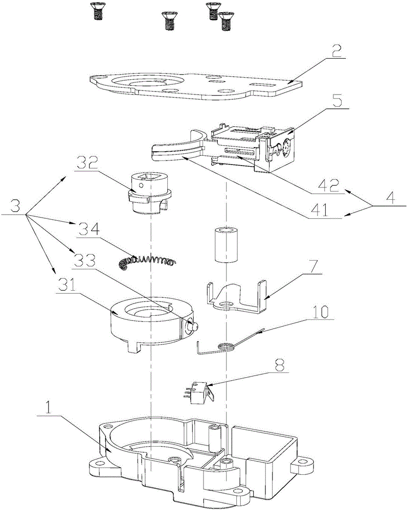
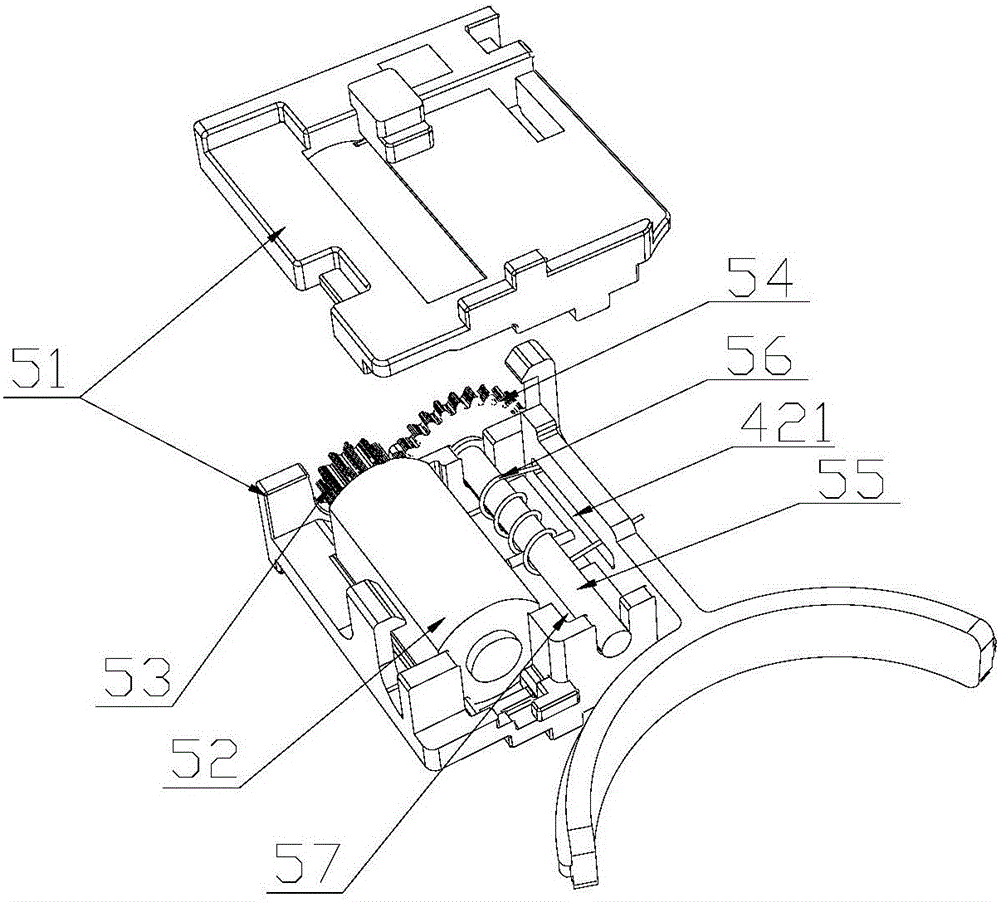
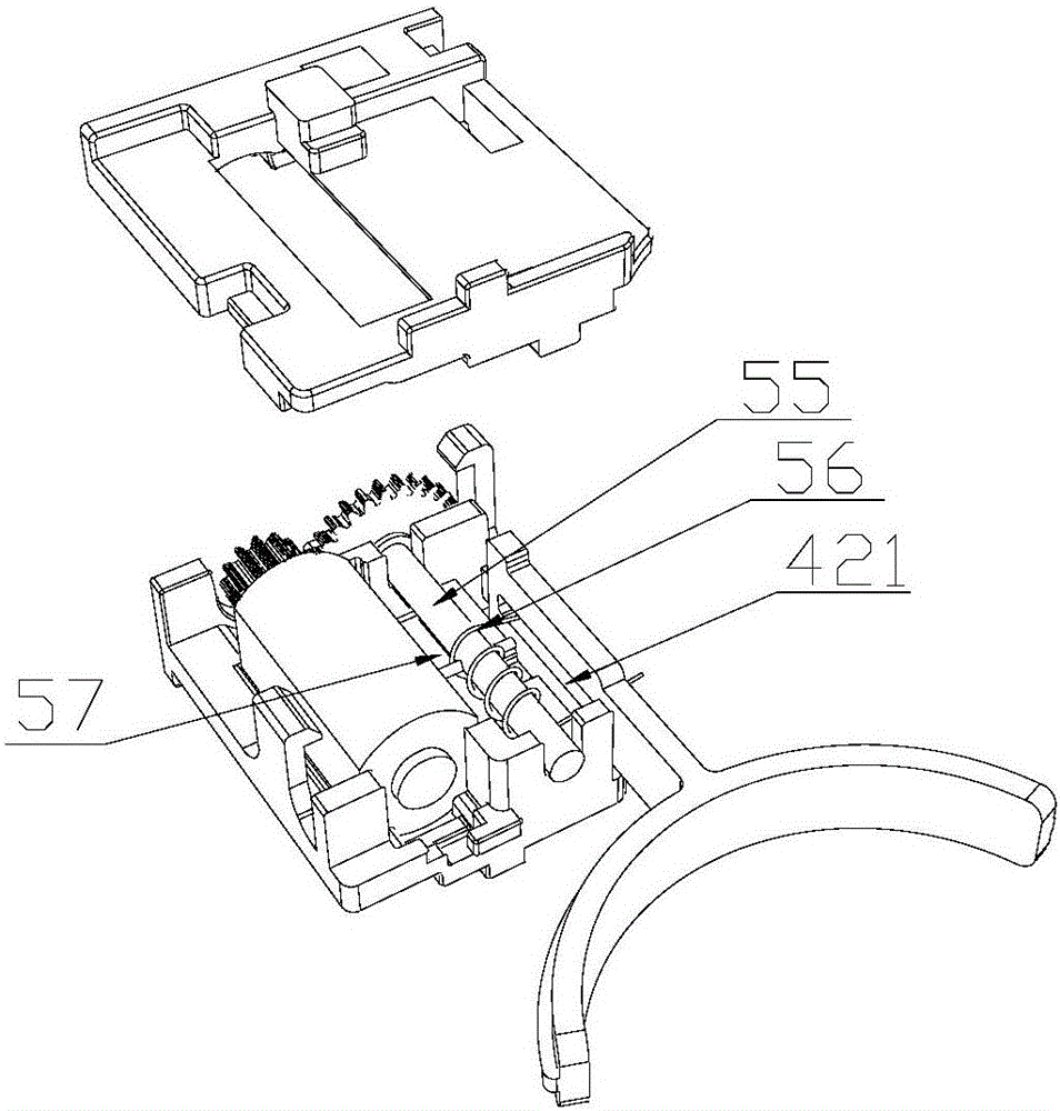
[0024] Such as figure 1 and Figure 4 , an external clutch device for an intelligent lock with good anti-theft performance, which is arranged on the inner side of the lock panel 9. The structure of the device includes a bottom case 1 and an upper cover 2 , and the bottom case 1 is provided with a clutch 3 , a clutch push block 4 , and a motor drive assembly 5 . The clutch 3 includes a clutch inner part 31 , a clutch outer part 32 , a latch 33 and a clutch inner part return spring 34 . The clutch push block 4 includes an arc-shaped push panel 41 and a panel push rod 42 . The arc-shaped pushing panel 41 is located outside the latch 33 ; the panel push rod 42 is disposed in the motor driving assembly 5 and can be driven by the motor driving assembly 5 to expand and contract on the motor driving assembly 5 . When the panel push rod 42 expands and contracts on the motor drive assembly 5, it drives the push panel 41 to push the latch 33 into the clutch inner part 31 and the clutc...


PUM


Abstract

The invention provides an external clutch device with the good anti-theft property and used for an intelligent lock. The external clutch device is disposed on the inner side of a lock panel and structurally comprises a bottom shell and an upper cover; a clutch, a clutch push block and a motor driving assembly are disposed in the bottom shell; the clutch push block comprises an arc-shaped push-pressing panel and a panel push rod; the push-pressing panel is located on the outer side of a bolt in the clutch; the panel push rod is arranged in the motor driving assembly and can extend or retract in the motor driving assembly; and the panel push rod pushes the push-pressing panel to push and press or keep away from the bolt of the clutch when extending or retracting in the motor driving assembly, so that the separation state or combination state of the clutch is achieved. The external clutch device for the door lock has the technical effects that the structure of the clutch is stable, alignment of separation and combination is more accurate, the separation and combination effect is better, and the anti-theft property is better.

Description

technical field [0001] The invention relates to a mechanical device of a door lock, in particular to an external clutch device for an intelligent lock with good anti-theft performance. Background technique [0002] Clutches for locks are generally divided into two types. The ones installed inside the lock body are called built-in clutches, while the clutches installed in the door handle structure are called external clutches. [0003] The door lock clutches on the market are all directly connected to the handle through square bars. This connection method has the following disadvantages: (1) The components that make up the clutch can only be set on the rotating shaft of the handle through superimposed square tongues, which will inevitably Increase the thickness of the lock panel so that there is enough space in the lock housing to place the clutch assembly. (2) The clutch of this structure, its components are all arranged on the handle shaft, easily destroyed, can not resist...

Claims


Application Information

Patent Timeline
IPC IPC(8): E05B17/00E05B9/00E05B47/00
CPCE05B9/002E05B17/00E05B47/00E05B2047/0026
Inventor 廖伟新
Owner 廖伟新
Learn More