Key-to-hole device with protective cover and method of use thereof

A technology of protective cover and key hole, applied in the field of locks, can solve the problems of ineffective lighting circuit, unfavorable light absorption, and not suitable for car door locks, etc.

Inactive Publication Date: 2018-09-28
CHONGQING IND POLYTECHNIC COLLEGE +1
View PDF2 Cites 0 Cited by
  • Summary
  • Abstract
  • Description
  • Claims
  • Application Information

AI Technical Summary

Problems solved by technology

In this way, the device can realize the illumination of the keyhole under weak light conditions, but the device needs to install additional circuits and control devices on the keyhole, which has a high cost, and does not need to illuminate the keyhole under strong light conditions. For lighting, the lighting circuit does not work at this time; as the Chinese invention patent specification CN201800629U announced on April 20, 2011, it discloses a lighting structure for an automobile ignition keyhole, including a circular fluorescent plate. A circular through hole is arranged in the center of the fluorescent plate, the diameter of the circular through hole is greater than the length of the car ignition key hole. The ignition keyhole of the car
Since the fluorescent light has a limited time, and the key of the car is usually under the steering wheel, the light is not good, and it is not conducive to the absorption of light by the fluorescent device.
[0004] In addition, the above-mentioned device is mainly suitable for the ignition key hole, because it does not have waterproof performance, it is not suitable for the car door lock facing the same problem

Method used


Image

  • Key-to-hole device with protective cover and method of use thereof
  • Key-to-hole device with protective cover and method of use thereof

Examples


Embodiment Construction

[0016] Below in conjunction with accompanying drawing and specific embodiment the present invention will be described in further detail:

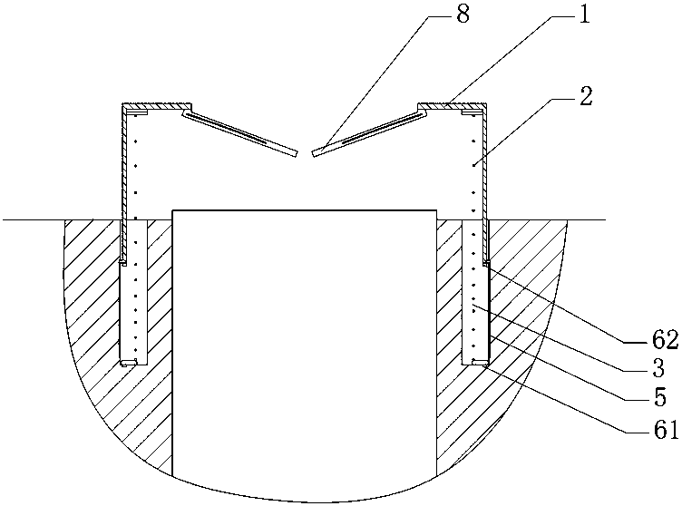
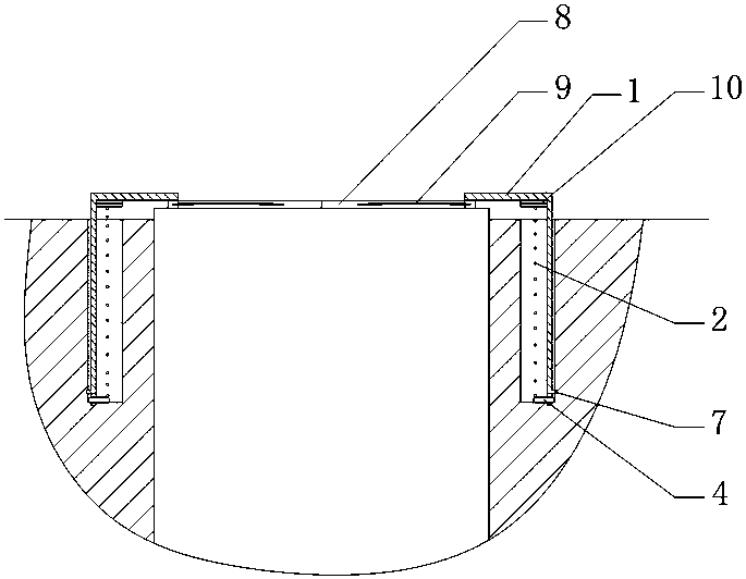
[0017] Such as figure 1 and figure 2 As shown: the present invention provides a key hole alignment device with a protective cover, including a protective cover 1 arranged above the key hole, the protective cover 1 is a metal stamping formed part, the protective cover 1 is cylindrical, and a spring is installed inside the protective cover 1 2 To realize the jacking of the protective cover 1, the side wall of the key hole is provided with a circular groove 3 to accommodate the side wall of the protective cover 1 and the spring 2, and the bottom of the circular groove 3 is provided with a sealing ring 4, and the cross section of the sealing ring 4 is rounded At least two L-shaped chutes 5 should be arranged on the side walls of the rectangular and circular trough 3, and three of them are arranged symmetrically here to improve stability. The...


PUM


Abstract

The invention relates to a vehicle lock, in particular to a key hole alignment device with a protecting cover. The key hole alignment device comprises the protecting cover arranged above a key hole. The protecting cover is cylindrical, a spring is arranged on the inner side of the protecting cover, and a round groove for containing the side wall of the protecting cover and the spring is formed in the side wall of the key hole. At least two L-shaped sliding grooves are formed in the side wall of the round groove. A lower magnetic block is arranged in the position, opposite to the innermost end of each sliding groove, of the bottom of the round groove. Protrusions clamped in the sliding grooves are arranged on the outer side of the protecting cover. Upper magnetic blocks attracting the lower magnetic blocks are arranged on the lower portion of the protecting cover. A round hole is formed in the center of the top of the protecting cover, and the diameter of the round hole is larger than the width of a key. The round hole is sealed by two semicircular elastic sheets arranged oppositely, the arc middles of the semicircular elastic sheets are flexibly connected with the round hole, and the middle of the bottom edge of each semicircular elastic sheet is provided with a spring sheet which is connected with the corresponding arc middle and bends downwards. By the adoption of the technical scheme, the key hole alignment device with the protecting cover is convenient to use and has the anti-blocking and waterproof functions.

Description

technical field [0001] The invention relates to a lockset, in particular to a key hole alignment device with a protective cover. Background technique [0002] In the case of low light, when the driver needs to insert the key into the keyhole of the car, motorcycle or electric vehicle to ignite, it is usually difficult to quickly find the position of the lockhole, which brings certain troubles to start the vehicle in time. [0003] In order to solve the above-mentioned problems, lighting circuits or lighting tools are generally added around the vehicle ignition keyhole, such as the Chinese invention patent specification of CN1393359A announced on January 29, 2003, which discloses a keyhole lighting device and its control. Method, the device includes a power supply, a lighting device, a control chip, a main switch and a sensing device. In this way, the device can realize the illumination of the keyhole under weak light conditions, but the device needs to install additional ci...

Claims


Application Information

Patent Timeline
Patent Type & Authority Patents(China)
IPC IPC(8): E05B17/18
CPCE05B17/18
Inventor 白云
Owner CHONGQING IND POLYTECHNIC COLLEGE
Why Eureka
Try Eureka