Steel wire rope winding device

A rope winder and wire rope technology, applied in the field of wire rope winders, can solve problems such as inconvenient operation of the wire rope, and achieve the effect of simple and convenient operation

Inactive Publication Date: 2017-04-26
JIANGYIN HUASHUO MACHINERY MFG
View PDF0 Cites 4 Cited by
  • Summary
  • Abstract
  • Description
  • Claims
  • Application Information

AI Technical Summary

Problems solved by technology

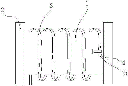
[0003] In order to solve the problem of inconvenient operation of the current steel wire rope when winding, the present invention provides a wire rope winder, which includes a rope winder body 1, and the two ends of the rope winder body 1 are provided with limiting bosses 2 , the wire rope 3 is wound on the rope winder body 1, a groove 4 is also provided on the rope winder body 1, a clip 5 is fixed in the groove 4, and one end of the wire rope 3 is fixed by the clip 5

Method used


Image

  • Steel wire rope winding device

Examples


Embodiment Construction

[0008] All features disclosed in this specification, or steps in all methods or processes disclosed, may be combined in any manner, except for mutually exclusive features and / or steps.

[0009] Any feature disclosed in this specification, unless specifically stated, can be replaced by other alternative features that are equivalent or have similar purposes. That is, unless expressly stated otherwise, each feature is one example only of a series of equivalent or similar features.

[0010] Such as figure 1 The wire rope winder shown includes a rope winder body 1, and the two ends of the rope winder body 1 are provided with limiting bosses 2, and the steel wire rope 3 is wound on the rope winder body 1, and the rope winder body 1 A groove 4 is also arranged on the top, and a clip 5 is fixed in the groove 4, and one end of the wire rope 3 is fixed by the clip 5. In the present invention, before winding, one end of the steel wire rope is clamped with a clip, and then the wire rope...


PUM


Abstract

The invention discloses a steel wire rope winding device. The steel wire rope winding device comprises a rope winding device body (1); limiting bosses (2) are arranged at the two ends of the rope winding device body (1); a steel wire rope (3) is wound on the rope winding device body (1); the rope winding device body (1) is further provided with a groove (4) in which a clamp (5) is fixed; and one end of the steel wire rope (3) is fixed through the clamp (5). According to the steel wire rope winding device, before winding, firstly, one end of the steel wire rope is clamped through the clamp, then, direct winding is performed, manual fixing is not needed, and operation is easy and convenient.

Description

technical field [0001] The invention relates to a wire rope winder. Background technique [0002] The existing rope winders all have smooth surfaces, and workers need to fix one end of the steel wire rope before winding it, otherwise the steel wire rope is difficult to wind on the rope winder, and the operation is quite inconvenient. Contents of the invention [0003] In order to solve the problem of inconvenient operation of the current steel wire rope when winding, the present invention provides a wire rope winder, which includes a rope winder body 1, and the two ends of the rope winder body 1 are provided with limiting bosses 2 The wire rope 3 is wound on the rope winder body 1, and a groove 4 is also provided on the rope winder body 1, and a clip 5 is fixed in the groove 4, and one end of the wire rope 3 is fixed by the clip 5. [0004] The beneficial effects of the present invention are: [0005] In the present invention, before winding, one end of the steel wire ro...

Claims


Application Information

Patent Timeline
Patent Type & Authority Applications(China)
IPC IPC(8): B65H75/28B65H75/14
Inventor 朱勤凤
Owner JIANGYIN HUASHUO MACHINERY MFG
Why Eureka
Try Eureka