
Strip coiling device with grabbing position, coiling position and unloading position arranged on rotating disc

A technology of a coiling device and a turntable, which is applied in the direction of coiling strips, transportation and packaging, and thin material processing, can solve problems such as safety accidents, large work, strip deformation, etc., to save energy, ensure stability, and avoid problems. The effect of security incidents

Active Publication Date: 2020-02-21
平邑经发科技服务有限公司
View PDF6 Cites 0 Cited by
  • Summary
  • Abstract
  • Description
  • Claims
  • Application Information

AI Technical Summary

Problems solved by technology

[0003] The traditional coiling device only needs to be composed of two baffles and a winding roller in the center. During the coiling process, the baffles need to be set up, and the strip is coiled by driving the baffles and the winding roller to rotate together, and the work is done. Larger, and after the coiling is completed, the traditional baffle is prone to roll when placed, causing safety accidents, and when the coiling starts, the traditional coiling device needs to manually fix the tape head on the winding roller , the operation is time-consuming and laborious, and in the coiling process, the drum formed by winding is not squeezed, and there will be gaps between the wound strip coils, which reduces the amount of strip coiling and also causes Deformation of the strip

Method used


Image

  • Strip coiling device with grabbing position, coiling position and unloading position arranged on rotating disc
  • Strip coiling device with grabbing position, coiling position and unloading position arranged on rotating disc
  • Strip coiling device with grabbing position, coiling position and unloading position arranged on rotating disc

Examples


Embodiment Construction

[0028] The following will clearly and completely describe the technical solutions in the embodiments of the present invention with reference to the accompanying drawings in the embodiments of the present invention. Obviously, the described embodiments are only some, not all, embodiments of the present invention. Based on the embodiments of the present invention, all other embodiments obtained by persons of ordinary skill in the art without making creative efforts belong to the protection scope of the present invention.

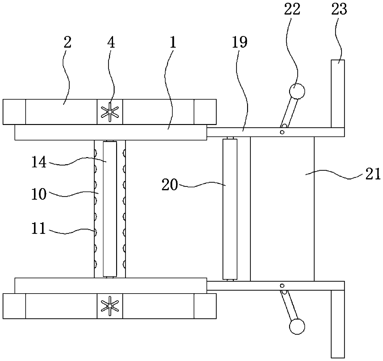
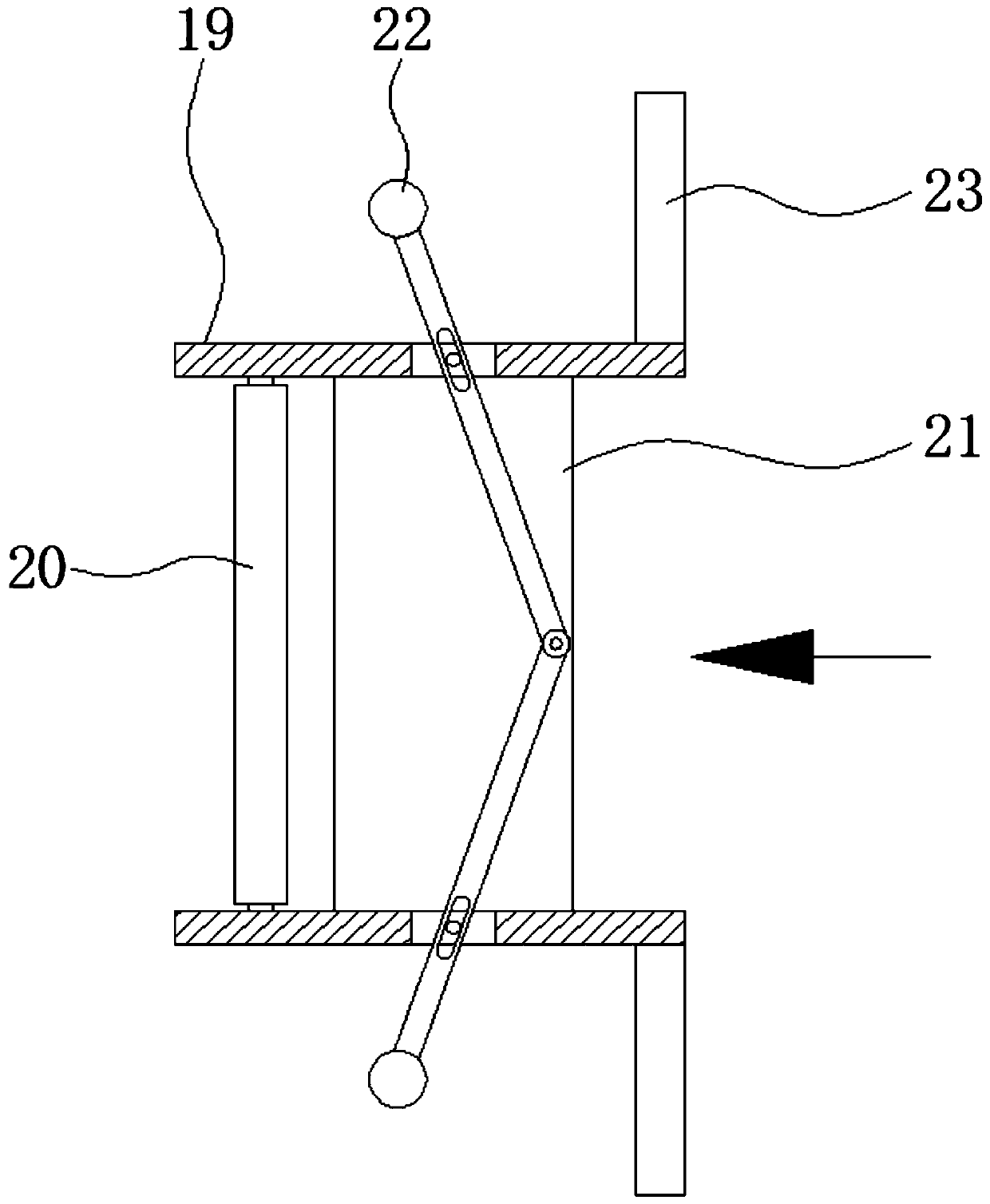
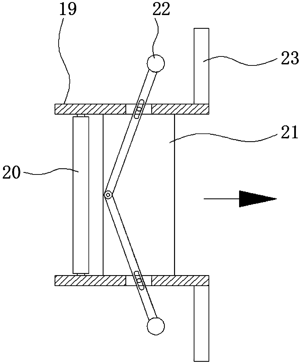
[0029] The embodiment of the strip coiling device that is provided with grabbing position, coiling position and unloading position on the turntable is as follows:

[0030] see Figure 1-7 , a strip coiling device with a grabbing position, a coiling position and an unloading position is set on the turntable, including a baffle 1, a support frame 2, a threaded rod 3, a knob 4, a first threaded sleeve 5, a connecting rod 6, and a slider 7 , universal wheel 8, ma...


PUM


Abstract

The invention provides a strip coiling device with a grabbing position, a coiling position and an unloading position arranged on a rotating disc, and relates to the technical field of strip coiling. The strip coiling device with the grabbing position, the coiling position and the unloading position arranged on the rotating disc comprises a baffle, wherein a supporting frame is fixedly mounted on the outer side of the bottom of the baffle, a threaded rod is rotationally connected to the inside of the supporting frame, a rotary knob is fixedly mounted at the top end of the threaded rod, and theperiphery of the threaded rod meshes with a first threaded sleeve. According to the strip coiling device with the grabbing position, the coiling position and the unloading position arranged on the rotating disc, the stability is improved when a strip is placed, the occurrence of safety accidents is avoided, a winding roller and the strip head of the strip can be automatically adsorbed, the manualfixation is not needed, the time and the labor are saved, in the coiling process, a roller formed by coiling the strip can be extruded continuously, the tightness of coiling is guaranteed, the coilingamount is improved, the strip can be flattened, and the longitudinal fold of the strip is avoided.

Description

technical field [0001] The invention relates to the technical field of strip coiling, in particular to a strip coiling device provided with a grabbing position, a coiling position and an unloading position on a turntable. Background technique [0002] The strip is a strip-shaped metal material supplied in coils with a large aspect ratio. It is produced by hot rolling or cold rolling. The thickness of the strip produced by the hot rolling method is relatively large. The cold rolling method can obtain what the hot rolling method cannot. Advantages, it can produce thinner strips with good surface quality, precise size and high mechanical properties. The thickness of the strips can be as thin as 0.001mm, and the strips need to be collected by coiling after the production is completed. For easy transportation and storage. [0003] The traditional coiling device only needs to be composed of two baffles and a winding roller in the center. During the coiling process, the baffles ne...

Claims


Application Information

Patent Timeline
Patent Type & Authority Applications(China)
IPC IPC(8): B65H18/10B65H18/26B65H19/30B65H18/02
CPCB65H18/028B65H18/10B65H18/26B65H19/30
Inventor 朱青松
Owner 平邑经发科技服务有限公司
Learn More