Al technical title is built by PatSnap Al team. It summarizes the technical point description of the patent document.
A technology for testing equipment and equipment, which is applied in the field of communication and can solve problems such as multiple plugging and unplugging of connecting wires
Active Publication Date: 2017-04-26
QINGDAO HISENSE MOBILE COMM TECH CO LTD
View PDF17 Cites 8 Cited by
Summary
Abstract
Description
Claims
Application Information
AI Technical Summary
This helps you quickly interpret patents by identifying the three key elements:
Problems solved by technology
Method used
Benefits of technology
Problems solved by technology
[0009] The invention provides a testing device for a mobile terminal, which is used to solve the problem in the prior art that the connecting wire needs to be plugged and unplugged multiple times during the testing process of the USB charging function and the OTG function of the mobile terminal.
Method used
Image
Click on the blue label to locate the original text in one second.
Reading with bidirectional positioning of images and text.
Examples
Embodiment 1
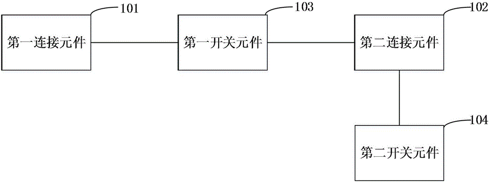
[0030] Based on the above discussion, a schematic structural diagram of a mobile terminal proposed by this application is as follows: figure 1 As shown, it includes a first connecting element 101 , a second connecting element 102 , a first switching element 103 and a second switching element 104 . The introduction of each important component is as follows:
[0031] (1) The first connecting element
[0032] In the embodiment of the present application, the testing device is connected to the charging device through the first connecting element. What is different from the prior art is that the charging device is directly connected to the mobile terminal when testing the charging function of the mobile terminal in the prior art. However, in the embodiment of the present application, the charging device is directly connected to the testing device, and then the testing device is connected to the mobile terminal.
[0033] In a preferred embodiment of the present application, the f...
Embodiment 2
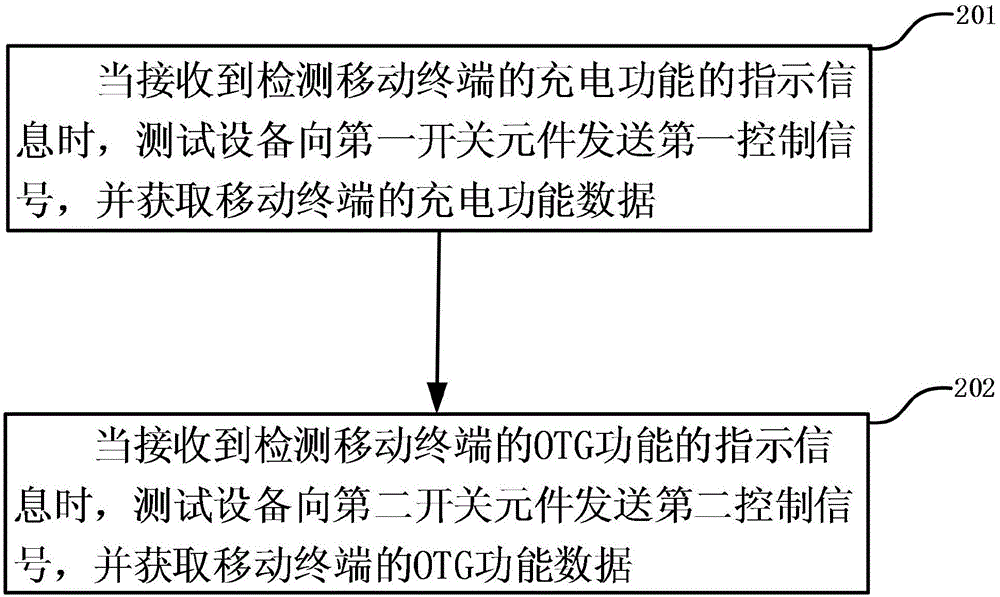
[0072] Based on the test equipment proposed in Embodiment 1, the present application proposes a test method to solve the problem that in the prior art, during the test process of the USB charging function and OTG function of the mobile terminal, it is necessary to plug and unplug the connecting wire many times. .
[0073] The method is applied to a system including a mobile terminal, a charging device, and the testing device as described in the first embodiment. Such as figure 2 Shown is a schematic flow chart of a test method proposed by the application, which at least includes the following steps:
[0074] S201. When receiving instruction information for detecting the charging function of the mobile terminal, the test device sends a first control signal to the first switch element, and acquires charging function data of the mobile terminal.
[0075] Wherein, the first control signal is used to instruct the first switch element to turn itself on, and to enable the charging...
PUM
Abstract
The invention provides a test device which comprises a first connecting element, a second connecting element, a first switch element and a second switch element, wherein the first connecting element is used for connecting with a charging device; the second connecting element is used for connecting with a mobile terminal; the first switch element is respectively connected with the first connecting element and the second connecting element and is used for charging the mobile terminal by the charging device when the first switch element is switched on, so that the test device can acquire a charging function data of the mobile terminal; the second switch element and the second connecting element are connected and grounded and are used for grounding an OTG control port of the mobile terminal when the second switch element and the second connecting element are switched on, so that the test device can acquire the OTG function data of the mobile terminal. Thus, the test for the charging function and the OTG function can be completed by only connecting the mobile terminal with the test device, so that the repeated processes of plugging and pulling the connecting wire can be avoided, the test efficiency is increased and the risk of scratching the mobile phone shell can be reduced.
Description
technical field [0001] The present invention relates to the field of communication technology, in particular to a test device, and at the same time, the present application also particularly relates to a test method. Background technique [0002] A USB charging function and an OTG (On-The-Go) function are two functions widely used in mobile terminals, both of which are realized by interacting with the mobile terminal through a USB port. However, when realizing these two functions, the roles played by the mobile terminal are different. When it is recognized that an OTG device is plugged in, the mobile terminal will set itself as a master device and supply power to the inserted external device through the USB port. At this time, the mobile terminal serves as a power supply device to supply power to the outside. While charging, the mobile terminal is a slave device that charges itself through an external power supply device. [0003] Due to the difference between the USB cha...
Claims
Application Information
Patent Timeline
Application Date:The date an application was filed.
Publication Date:The date a patent or application was officially published.
First Publication Date:The earliest publication date of a patent with the same application number.
Issue Date:Publication date of the patent grant document.
PCT Entry Date:The Entry date of PCT National Phase.
Estimated Expiry Date:The statutory expiry date of a patent right according to the Patent Law, and it is the longest term of protection that the patent right can achieve without the termination of the patent right due to other reasons(Term extension factor has been taken into account ).
Invalid Date:Actual expiry date is based on effective date or publication date of legal transaction data of invalid patent.