Electric fuse memory unit and electric fuse memory array

A technology of memory cells and memory arrays, applied in the field of semiconductors, to achieve the effect of improving the speed of read operations

Inactive Publication Date: 2017-04-26
SEMICON MFG INT (SHANGHAI) CORP +1
View PDF3 Cites 1 Cited by
  • Summary
  • Abstract
  • Description
  • Claims
  • Application Information

AI Technical Summary

Problems solved by technology

[0006] Therefore, it is necessary to propose a new capacitive wire storage unit and electric fuse storage array to solve the problem of using a static memory (SRAM) to first store a small-capacity storage in some high-speed applications. The problem of reading data to meet the unlimited number of reads and the read speed synchronized with the system

Method used


Image

  • Electric fuse memory unit and electric fuse memory array
  • Electric fuse memory unit and electric fuse memory array
  • Electric fuse memory unit and electric fuse memory array

Examples


Embodiment 1

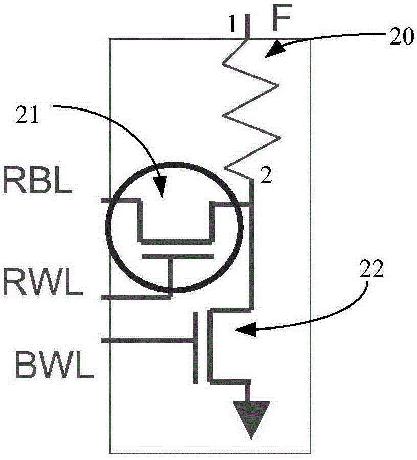
[0046] Below, refer to figure 2 An eFuse storage unit proposed by an embodiment of the present invention will be described.

[0047] Exemplarily, as figure 2 As shown, the eFuse storage unit of the present invention includes the following elements:

[0048] An electric fuse 20 is included, and the electric fuse 20 has a first end 1 and a second end 2 opposite to the first end 1 . The first end of the electric fuse is connected to a second bit line (not shown).

[0049] Exemplarily, the material of the electric fuse 20 may include polysilicon. Wherein the first end 1 is the anode of the electric fuse 20 , and the second end is the cathode of the electric fuse 20 .

[0050] It also includes a first transistor 21, the drain of the first transistor 21 is connected to the second end 2 of the electric fuse 20, the gate of the first transistor 21 is connected to the read word line RWL, and the first A source of a transistor 21 is connected to the read bit line RBL. The first ...

Embodiment 2

[0060] Another embodiment of the present invention further provides an electric fuse storage array, which includes the electric fuse storage unit in the foregoing embodiments.

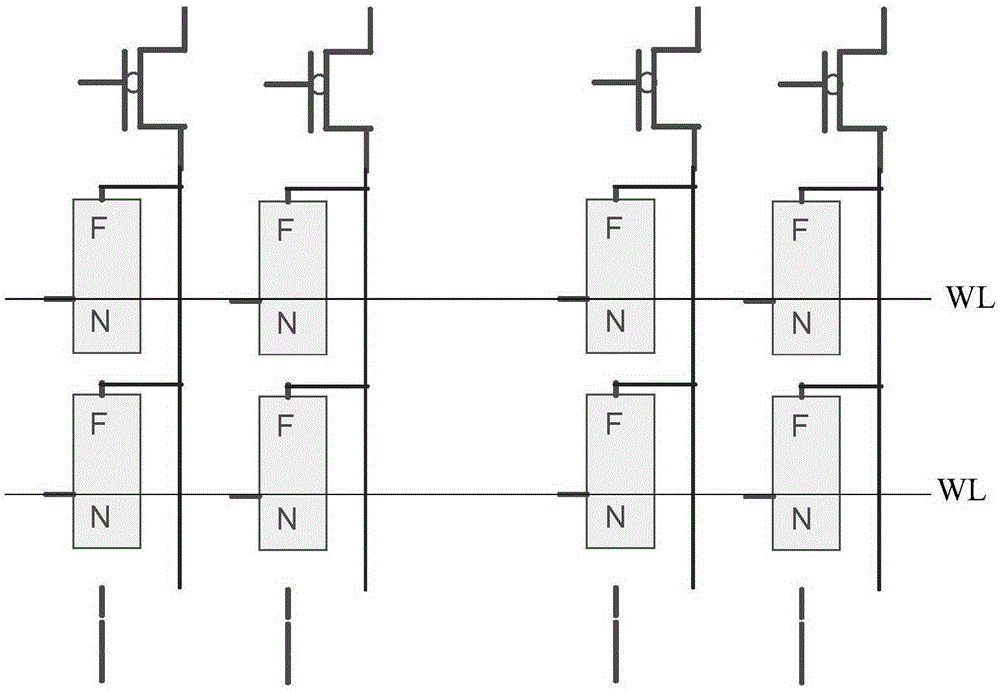
[0061] Specifically, refer to image 3 The electric fuse memory array in the embodiment of the present invention is described in detail.

[0062] The electric fuse storage array of this embodiment includes several electric fuse memory cells 30, and the several electric fuse memory cells 30 are arranged in multiple rows and multiple columns, for example, arranged in m rows and n columns, wherein m and n is an integer.

[0063] The electric fuse memory array in the embodiment of the present invention also includes several PMOS transistors 31, and the drain of each of the PMOS transistors 31 is connected to the second bit line BL2 of the column where it is located, and the number of the PMOS transistors can be equal to the electric The number of columns of fuse memory cells, for example, if several elec...


PUM


Abstract

The present invention provides an electric fuse memory unit and an electric fuse memory array, and relates to the technical field of semiconductors. The electric fuse memory unit comprises: an electric fuse provided with a first terminal and a second terminal opposite to the first terminal; a first transistor, wherein the drain electrode of the first transistor is connected to the second terminal of the electric fuse, the grid electrode of the first transistor is connected to a read word line, and the source electrode of the first transistor is connected to a first bit line; and a second transistor, wherein the drain electrode of the second transistor is connected to the second terminal of the electric fuse, and the grid electrode of the second transistor is connected to a fusing word line. According to the embodiments of the present invention, the NMOS transistor transmission gate connected to the read word line is additionally arranged between the electric fuse and the second transistor to separate the read and the write so as to limit the flowing read current, such that the number of the read operations is not limited, and the read operation speed of the electric fuse memory unit can be improved through the new read time sequence.

Description

technical field [0001] The invention relates to the technical field of semiconductors, in particular to an electric fuse storage unit and an electric fuse storage array. Background technique [0002] In the field of semiconductor technology, the electronically programmable fuse (eFuse) technology is widely used as a one-time programmable (OTP) memory in many circuits due to its compatibility with CMOS logic devices and ease of use. [0003] According to the theory of electromigration, eFuse technology stores information by whether the electric fuse is blown by the current. The resistance of the polysilicon electric fuse is very small before it is blown, and the resistance can be regarded as infinite after continuous high-current blown, and the electric fuse is broken. status will be maintained permanently. eFuse technology has been widely used in redundant circuits to improve the problem of chip failure or the ID of the chip, the basic code of the device, etc., to replace t...

Claims


Application Information

Patent Timeline
Patent Type & Authority Applications(China)
IPC IPC(8): G11C17/16
Inventor 杨家奇
Owner SEMICON MFG INT (SHANGHAI) CORP
Why Eureka
Try Eureka