A Dual Power Amplifier Circuit

A power amplifier, dual power supply technology, used in amplifiers, differential amplifiers, amplifiers with semiconductor devices/discharge tubes, etc., can solve crossover distortion, bias voltage is not easy to adjust, dual power supply power amplifier circuit power tube characteristics Change and other problems to achieve the effect of automatic calibration and avoid crossover distortion

Active Publication Date: 2020-01-21
THE 41ST INST OF CHINA ELECTRONICS TECH GRP
View PDF7 Cites 0 Cited by
  • Summary
  • Abstract
  • Description
  • Claims
  • Application Information

AI Technical Summary

Problems solved by technology

When using diodes for bias compensation, the bias voltage is not easy to adjust, so it is not often used
Designers typically use V BE Expand the circuit for bias compensation, and calibrate the bias voltage before the product leaves the factory. However, when analyzing and testing semiconductor devices, due to the different test environments, especially the influence of ambient temperature, the characteristics of the power tube of the dual-supply power amplifier circuit will change. , the bias voltage needs to be automatically calibrated, otherwise there will be crossover distortion

Method used


Image

  • A Dual Power Amplifier Circuit
  • A Dual Power Amplifier Circuit
  • A Dual Power Amplifier Circuit

Examples


Embodiment Construction

[0017] The following will clearly and completely describe the technical solutions in the embodiments of the present invention with reference to the accompanying drawings in the embodiments of the present invention. Obviously, the described embodiments are only some, not all, embodiments of the present invention. Based on the embodiments of the present invention, all other embodiments obtained by persons of ordinary skill in the art without making creative efforts belong to the protection scope of the present invention.

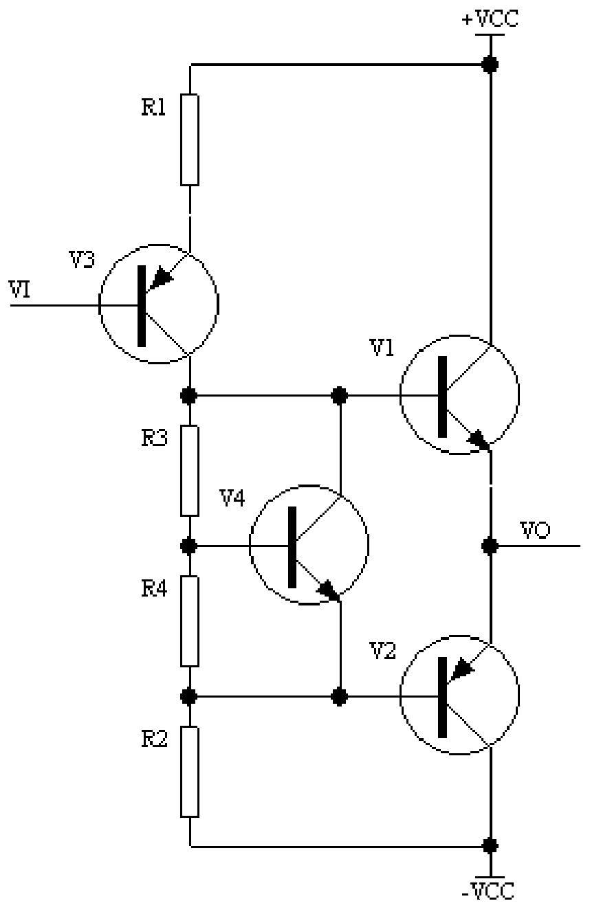
[0018] See Figure 4 , a dual-supply power amplifier circuit, comprising an input circuit, a bias circuit and an output circuit;

[0019] See Figure 4 , the input circuit includes PNP transistor V3, NPN transistor V5, NPN transistor V6, NPN transistor V7, NPN transistor V8, capacitor C1, feedback compensation capacitor C2, feedback resistor Rf, resistor R1, resistor R5, resistor R6, resistor R11, resistor R12, resistor R13, resistor R14, resistor R15, resis...


PUM


Abstract

The invention discloses a dual-power power amplifier circuit, comprising an input circuit, a bias circuit, and an output circuit. The bias circuit is formed by a NPN transistor V4, resistors R2-R4, a capacitor C3, and a digital bias circuit. The digital bias circuit comprises a field-programmable gate array FPGA, a opto-coupler isolation circuit, and a programmable digital potentiometer D1. Two output ends of the programmable digital potentiometer D1 are respectively connected with the other end of the resistor R2 and the other end of the resistor R3. The field-programmable gate array FPGA is used to generate a control signal of the programmable digital potentiometer, and the programmable digital potentiometer generates required variable resistance, to form a VBE expansion circuit, so as to adjust bias voltage of a power tube. The dual-power power amplifier circuit realizes digital design of a bias circuit, prevents crossover distortion, and realizes automatic calibration.

Description

technical field [0001] The invention relates to the related technical field of semiconductor device analysis, in particular to a dual power supply power amplifier circuit. Background technique [0002] With the development of semiconductor device manufacturing technology, power electronics technology and the demand for complex automatic testing, conventional voltage-current (IV) measurement and capacitance-voltage (CV) measurement can no longer meet the needs of semiconductor device testing, and high-precision high-current pulses are required source to test its dynamic performance characteristics. [0003] The block diagram of a commonly used DC input high current pulse source is as follows: figure 1 shown. Composed of DC-DC conversion, pulse generation, control circuit, drive isolation circuit, sampling circuit, auxiliary power supply and man-machine interface, there are three key circuits in the block diagram: DC-DC conversion, pulse generation and control circuit, espec...

Claims


Application Information

Patent Timeline
Patent Type & Authority Patents(China)
IPC IPC(8): H03F1/32H03F3/45
CPCH03F1/3211H03F3/4508
Inventor 王俊李斌王文廷吕士如
Owner THE 41ST INST OF CHINA ELECTRONICS TECH GRP
Why Eureka
Try Eureka