

Hand-push type grain cutter
A hand-push and push-rod technology, applied in the field of mowers, can solve problems such as laborious and difficult to use, and achieve the effects of simple production, increased storage capacity, and improved labor efficiency
Inactive Publication Date: 2017-05-10
长沙智通知识产权服务有限公司
View PDF0 Cites 2 Cited by
- Summary
- Abstract
- Description
- Claims
- Application Information
AI Technical Summary
Problems solved by technology
[0004] The purpose of the present invention is to solve the shortcoming of being laborious and difficult to use in the prior art, and propose a hand-push mower
Method used
View moreImage
Smart ImageViewing Examples

Examples
Embodiment approach
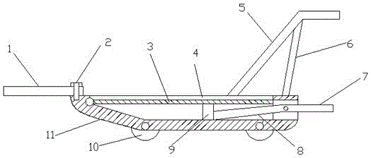
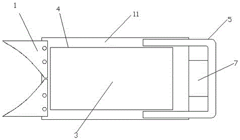
[0022] Implementation method: the laborer grasps the push rod 5 and pushes it, and the small wheel 10 reduces the resistance when sliding, so that it can also be pushed in a dry land. The cutter 1 cuts off the rice, and the cut rice is poured into the storage tank 4, and the storage tank 4. To increase the storage capacity, by stepping on the pedal 7, the movable bottom plate 3 can be lifted by using the principle of leverage, and the unloading can be easily completed, saving time and effort.
Login to View More PUM
 Abstract
The invention relates to the technical field of grain cutters, in particular to a hand-push type grain cutter. The grain cutter includes a sliding type machine body, two cutters are arranged at the end of the sliding type machine body, a push rod is connected with the upper portion of the sliding type machine body, four small wheels are rotatably installed at the bottom of the sliding type machine body, the upper portion of the sliding type machine body is provided with a storage tank, the bottom of the storage tank is provided with a movable bottom plate, one side of the movable bottom plate is rotatably installed on the sliding type machine body, the lower portion of the movable bottom plate is provided with an ejector rod, the ejector rod is connected with a connection rod, the connection rod is rotatably installed on the sliding type machine body, and the end of the connection rod extends to the outside of the sliding type machine body and is connected with a pedal. The bottom is provided with the small wheels, the streamline bottom plate is cooperated with the small wheels to make pushing save more labor, the arrangement of the storage tank and the movable bottom plate increases the storage capacity and can be cooperated with the pedal to make unloading easily, and the labor efficiency is thus effectively improved. The grain cutter is simple to manufacture, saves labor, is convenient to use, and is suitable for use in both a paddy field and dry soil.
Description
technical field [0001] The invention relates to the technical field of grain cutters, in particular to a hand-push grass cutter. Background technique [0002] Farmers generally use hand-held sickles to harvest rice. Its disadvantage is that because the rice is relatively short, farmers must bend over to operate during the whole harvesting process, and it is easy to cut hands and feet, and the labor efficiency is low. Therefore, farmers hope to have a farm tool that can harvest rice without bending over. [0003] Someone has designed a hand-push grain cutter for this reason, but because the structure is relatively simple, it is not very convenient to load and unload materials, and it is very laborious to rely entirely on the bottom to slide forward. Contents of the invention [0004] The purpose of the present invention is to solve the shortcoming of being laborious and difficult to use in the prior art, and proposes a hand push type crop cutter. [0005] In order to achi...
Claims
Login to View More Application Information
Patent Timeline
 IPC IPC(8): A01D45/04A01D67/00
CPCA01D45/04A01D67/00
Inventor杨忠淮
Owner长沙智通知识产权服务有限公司