Low pressure valve release device and its installation method
A low-pressure valve and releaser technology, which is applied in fire rescue and other directions, can solve the problems of unable to replenish the pressure of the fire extinguisher and leakage of the valve of the fire extinguisher, and achieve the effects of solving the leakage of the valve of the fire extinguisher, prolonging the service life, and being convenient to use
- Summary
- Abstract
- Description
- Claims
- Application Information
AI Technical Summary
Problems solved by technology
Method used
Image

Examples
Embodiment 1
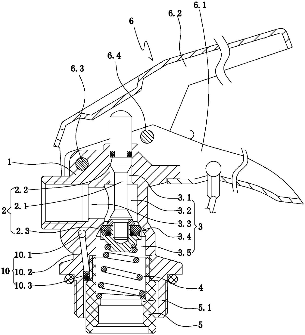
[0040] Embodiment 1: as figure 1As shown, a low-pressure valve release device includes a valve body 1; a valve body flow channel 3 arranged in the valve body; a valve core 2 for controlling the flow channel of the valve body; a riser sleeve 5; The first return spring 4; the pressure supplement mechanism 10 arranged on the valve body; the safety release device 11 and the fire extinguisher operating handle 6 arranged on the valve body.
[0041] The flow channel of the valve body includes a main channel running through the upper and lower ends of the valve body, and a valve body outlet 3.3 arranged on the outer side of the valve body and communicating with the main channel. The lower port of the main channel constitutes the inlet of the valve body. The main channel includes an upper valve hole 3.1, a middle valve hole 3.2 located below the upper valve hole, a tapered valve hole 3.4 whose inner diameter gradually decreases from bottom to top, and a lower valve hole 3.5 located be...
Embodiment 2
[0056] Embodiment 2: An installation method of a low-pressure valve releaser. For the specific structure of the low-pressure valve releaser of this embodiment, refer to Example 1: The installation method of a low-pressure valve releaser includes the following steps:
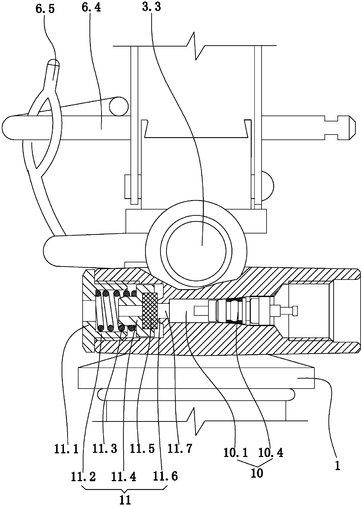
[0057] First: Install the safety release device on the valve body: First, glue the rubber pressing block on the rubber mounting block; then, put the rubber mounting block into the mounting hole; then, put the pre-tightened compression spring into the In the installation hole; finally, the limit sleeve body is installed in the installation hole, and the limit sleeve body and the installation hole are connected by threads. One end of the pre-tightened compression spring extends into the limit sleeve body and abuts against the limit block of the sleeve body, and the other end of the pre-tightened compression spring is sleeved on the spring limit boss. The rubber pressing piece is pressed against the end of the annul...
Embodiment 3
[0061] Embodiment 3: the remaining structure of this embodiment is with reference to embodiment 1, and its difference is:
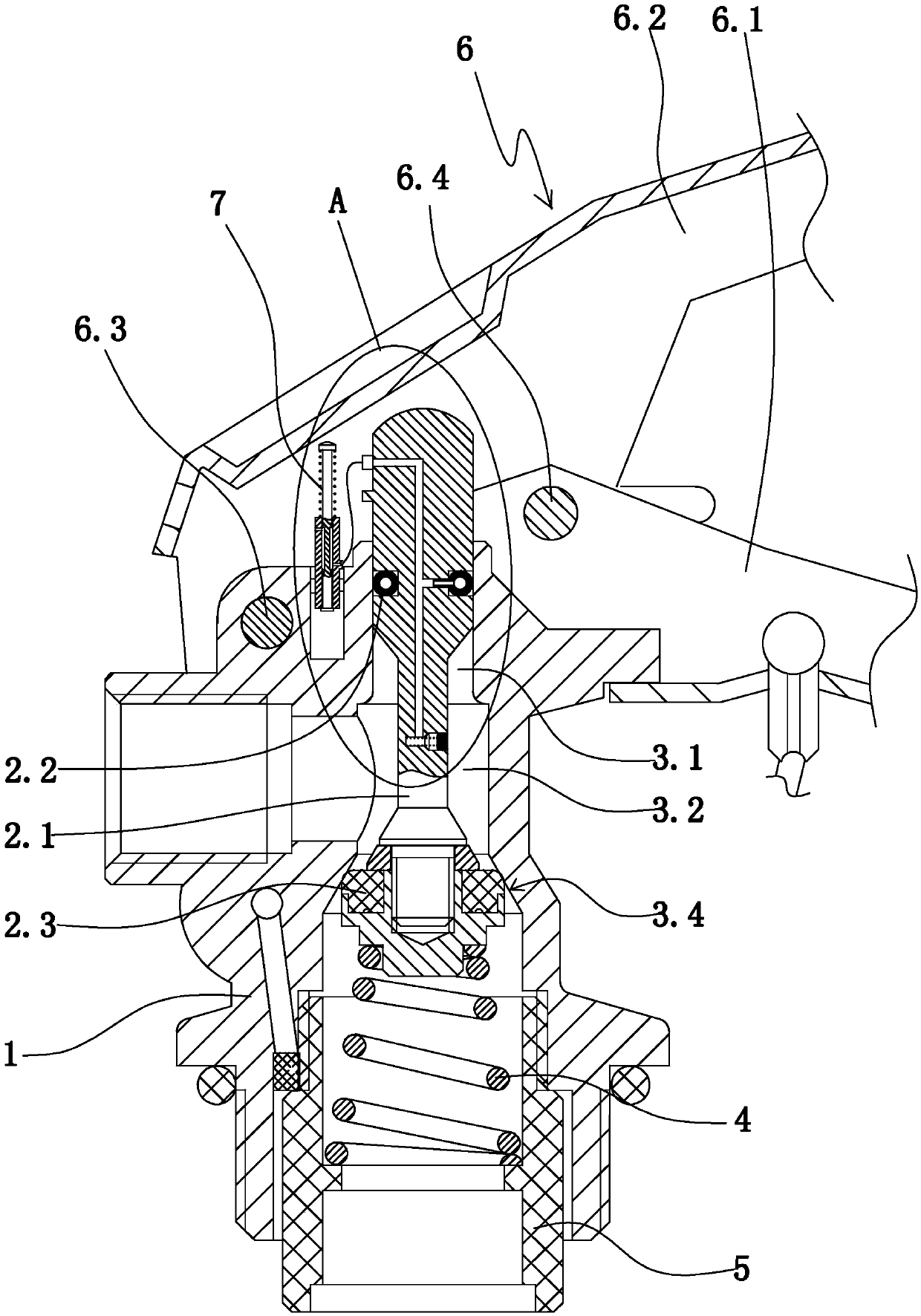
[0062] Such as figure 2 , image 3 As shown, a low pressure valve release device also includes an adaptive inflation and exhaust sealing structure. A sealing ring installation groove on the valve stem is arranged on the outer surface of the valve stem. The sealing ring on the valve stem is arranged in the installation groove of the sealing ring on the valve stem. An annular air-filling cavity 2.4 is arranged in the sealing ring on the valve stem. The outer surface of the sealing ring on the valve stem is also provided with an inflation intubation tube 2.5 communicating with the annular inflation chamber.
[0063] The adaptive inflation and exhaust sealing structure includes an adaptive on-off mechanism 7, a pressure-type inflation structure 8 and a main channel 9 in the valve stem.
[0064] Such as image 3 , Figure 4 As shown, the pressure-type ...
PUM
 Abstract
Description
Claims
Application Information