The method of adjusting the stiffness by changing the structural size of the pivoting arm joints and the pivoting arm joints

A technology of node structure and torsional rigidity, applied in the field of locomotive parts manufacturing, can solve problems such as axle bearing wear

Active Publication Date: 2019-01-22
ZHUZHOU TIMES RUIWEI ANTI VIBERATION EQUIP LTD
View PDF10 Cites 0 Cited by
  • Summary
  • Abstract
  • Description
  • Claims
  • Application Information

AI Technical Summary

Problems solved by technology

[0011] The purpose of the present invention is to propose a method for preventing or reducing the wear of the locomotive axle bearing and the joint of the joint of the joint of the joint of the joint of the joint of the joint of the joint of the joint of the joint of the joint of the joint of the joint of the joint of the joint of the joint of the joint of the joint of the joint of the joint

Method used


Image

  • The method of adjusting the stiffness by changing the structural size of the pivoting arm joints and the pivoting arm joints
  • The method of adjusting the stiffness by changing the structural size of the pivoting arm joints and the pivoting arm joints

Examples


Embodiment 1

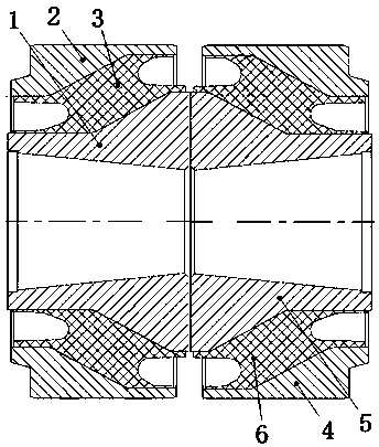
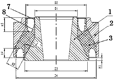
[0034] Attached figure 1 with 2 A specific embodiment of the present invention is given; a swing arm node includes a left metal outer sleeve 2 and a left metal inner sleeve 1. A left rubber layer 3 is integrally vulcanized between the left metal outer sleeve 2 and the left metal inner sleeve 1, As well as the right metal outer sleeve 4 and the right metal inner sleeve 5, a right rubber layer 6 is integrally vulcanized between the right metal outer sleeve 4 and the right metal inner sleeve 5; the inner holes of the left metal inner sleeve 1 and the right metal inner sleeve 5 are cones respectively The holes are arranged facing each other, that is, the big head of the cone hole is outside, and the small head of the cone hole is close to each other on the inner back and back; the characteristic is that the inner diameter of the inner sleeve of the rotating arm node is set to 90~93mm and the outer diameter D3 128~132mm; The inner diameter D2 of the outer sleeve diameter is set to 12...

Embodiment 2

[0039] The structure of the second embodiment is basically the same as that of the first embodiment, except that the inner diameter of the inner sleeve of the boom node is set to 91~92mm, and the outer diameter is set to 129~130mm; the inner diameter of the outer sleeve is set to 129~130mm, and the outer diameter The diameter is set to 171~172mm; and to ensure the matching of the diameter size of the inner sleeve and outer sleeve of the boom node, the longitudinal stiffness of the boom node can be controlled at 11-13KN.mm -1 , The axial stiffness is controlled at 6-8KN.mm -1 , Thereby reducing the lateral load of the vehicle when passing through the curve at high speed, and reducing the wear of the bearing inside the axle box. .

Embodiment 3

[0041] The structure of the third embodiment is basically the same as that of the second embodiment, except that the groove size of the small diameter end is controlled to 23~26mm; the groove size of the large diameter end is controlled to 15~18mm. The digging groove is used to reduce the node of the boom. Radial stiffness improves the axial stiffness of the boom node, so that the longitudinal stiffness of the boom node is controlled at 11-13KN.mm -1 , The axial stiffness is controlled at 6-8KN.mm -1 , Thereby reducing the lateral load of the vehicle when passing through the curve at high speed, and reducing the wear of the bearing inside the axle box.


PUM


Abstract

A method for adjusting the rigidity by changing the structural size of a rotation arm node can improve the rigidity matching performance of the rotation arm node by changing the structural size of the rotation arm node. A two tapered inner hole rotation arm node combined structure is adopted, the rigidity performance of the rotation arm node is changed by changing the size of a rubber profile of the rotation arm node and the diameter size of an inner sleeve and an outer sleeve of the rotation arm node, and then the longitudinal rigidity and the deflection rigidity of the rotation arm node are lowered. The rigidity of the rotation arm node is adjusted by matching the size of the rubber profile and the diameter size of the inner sleeve and the outer sleeve of the rotation arm node, the longitudinal rigidity and the deflection rigidity of the rotation arm node are lowered, and the longitudinal rigidity of the rotation arm node is controlled in 11-13 KN.mm<-1>; the deflection rigidity is lowered by controlling the longitudinal rigidity, the axial rigidity is improved, the axial rigidity of the rotation arm node is controlled in 6-8 KN.mm<-1>, and the torsional rigidity will not decrease. The experiment proves that the method can effectively prevent or relieve abrasion of bearings in a axle box.

Description

Technical field [0001] The present invention relates to a method and device for adjusting the performance of locomotive components, in particular to a method for preventing or reducing the wear of the axle box bearing of a locomotive by changing the performance of a locomotive arm node, and the arm node to improve the locomotive axle box The service life of the bearing. It belongs to the technical field of locomotive parts manufacturing. Background technique: [0002] Boom type axle box positioning method is a traditional axle box positioning method, which is widely used in light rail, subway, ordinary passenger cars and high-speed EMU bogies. The so-called rotary arm axle box positioning is to combine the axle box and the positioning rotary arm to form the rotary arm shaft, and the axle box and the positioning rod are integrated to form the rotary arm structure. The positioning of the pivoting arm of the axle box is connected with the frame mounting seat through a node at one ...

Claims


Application Information

Patent Timeline
IPC IPC(8): B61F5/30
Inventor 蒋仲三冯万盛林胜何海军罗俊陈俊辉
Owner ZHUZHOU TIMES RUIWEI ANTI VIBERATION EQUIP LTD
Why Eureka
Try Eureka