Automatic buckling and pressing type spraying aerosol can

A technology of automatic spraying and aerosol cans, applied in the direction of liquid distribution, etc., can solve the problems of low efficiency, high spraying cost, inconvenient operation, etc., and achieve the effect of reducing labor intensity, good spraying effect and low production cost.

Active Publication Date: 2017-05-10
广东自由能科技股份有限公司
View PDF12 Cites 0 Cited by
  • Summary
  • Abstract
  • Description
  • Claims
  • Application Information

AI Technical Summary

Problems solved by technology

The manual nozzle spraying method is labor-intensive for the operator, and the nozzle needs to be pressed all the time to achieve continuous spraying, which is not efficient; the special spray gun is expensive and inconvenient to operate

Method used


Image

  • Automatic buckling and pressing type spraying aerosol can
  • Automatic buckling and pressing type spraying aerosol can
  • Automatic buckling and pressing type spraying aerosol can

Examples


Embodiment 1

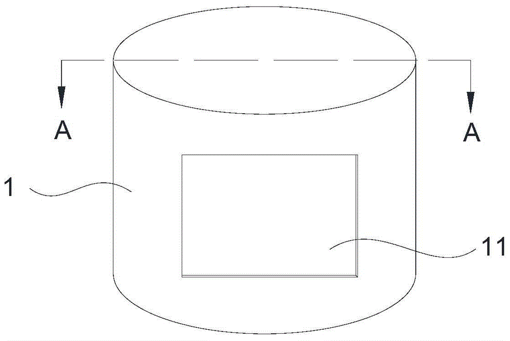
[0018] Such as Figure 1-4 As shown, the buckle type automatic spraying aerosol can includes a gland 1 and a tank body 2 . One end of the tank body 2 is formed with a valve cover 21, and the top of the valve cover 21 is provided with a spray head 23, and the aerosol can sprays aerosol by pressing the spray head 23. The gland 1 can be sleeved on the valve cover 21 of the tank body 2 .

[0019] The side of the gland 1 is provided with an injection port 11 corresponding to the spray hole 24 on the spray head 23 . The gland 1 is sleeved on the valve cover 21 , and when the spray head 23 is pressed, the aerosol in the tank body 2 can be sprayed out from the injection port 11 .

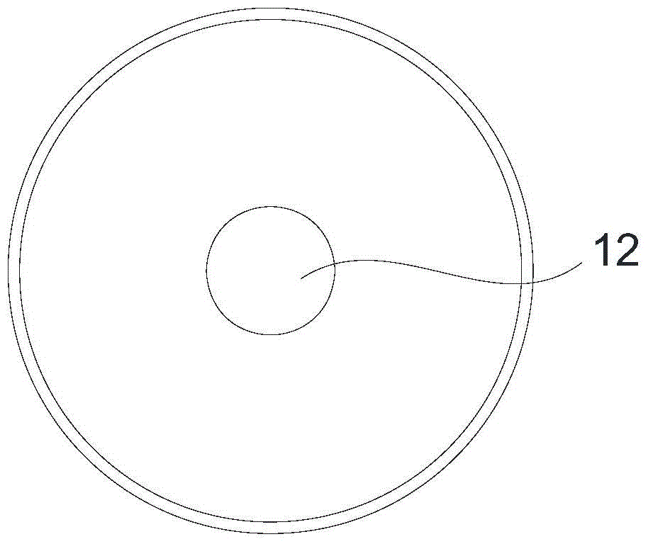
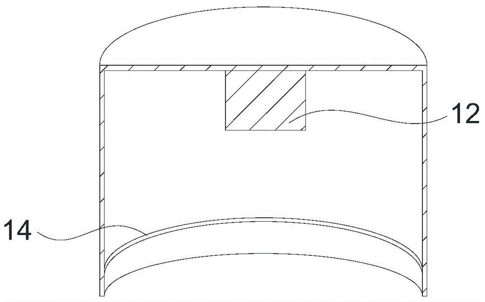
[0020] The bottom of the gland 1 is provided with a solid pillar 12 corresponding to the pressing end of the spray head 23 , and the inner wall is provided with a slot, which is a groove 14 surrounding the inner wall of the gland 1 .

[0021] The outer wall of the valve cover 21 of the tank body 2 is pro...

Embodiment 2

[0024] Such as Figure 5 , 6 As shown, the difference between this embodiment and the buckle-type automatic spraying aerosol can of Embodiment 1 is that the inner wall of the gland 1 of the buckle-type automatic spraying aerosol can of this embodiment is provided with a card slot 15 and a groove 16 ; Valve cover 21 is provided with a convex ring 26 .

[0025] When the protruding ring 26 and the locking groove 15 are buckled and fixed, the top of the pillar 12 is connected to the pressing end of the spray head 23, and the spray head 23 is in a closed state. When the protruding ring 25 is engaged with the groove 16, the strut 12 compresses the spray head 23 to be in a state of maximum compression.

Embodiment 3

[0027] Such as Figure 7 As shown, the difference between this embodiment and the buckle-type automatic spraying aerosol can of Embodiment 2 is that a limiting groove 17 for fitting the protruding ring 25 is also provided between the slot 15 and the groove 16 of the gland 1 .


PUM


Abstract

The invention discloses an automatic buckling and pressing type spraying aerosol can which comprises a can body and a gland. A valve cover is formed on the can body. A spray nozzle for jetting aerosol by being pressed is arranged at the top end of the valve cover. The valve cover is sleeved with the gland. A limiting buckle for fixing the gland and the valve cover is arranged between the gland and the valve cover. The gland is provided with a jet port which corresponds to a spray hole in the spray nozzle. When the gland and the valve cover are fixed through the limiting buckle, the bottom of the gland compresses the spray nozzle so that the spray nozzle can be in a spraying state. According to the automatic buckling and pressing type spraying aerosol can, automatic spraying of the spraying can is achieved through buckling of the gland and the valve cover, and spraying can be carried out with different spray flows according to the different buckling positions of the gland and the valve cover, so that the operation mode of carrying out spraying through continuous pressing with hands or through a special spray gun in the existing aerosol hand-spray industry is changed, the labor intensity is relieved, the spraying effect is good, and the manufacturing cost is low.

Description

technical field [0001] The invention relates to an aerosol can, in particular to a buckle type automatic spraying aerosol can. Background technique [0002] At present, the aerosol cans for automatic aerosol spraying generally adopt two methods of spraying with a hand-pressed spray nozzle or spraying with a special spray gun. The manual nozzle spraying method is laborious for the operator, and the nozzle needs to be pressed all the time to achieve continuous spraying, which is not efficient; the special spray gun is expensive and inconvenient to operate. Therefore, it is necessary to propose a spray can that can not only achieve automatic spraying, but also be simple, labor-saving and efficient for operators. Contents of the invention [0003] In order to solve the above problems, realize the automatic spraying of aerosol cans, achieve the purpose of simple, labor-saving and high-efficiency operators, and promote the development of the aerosol industry, the present invent...

Claims


Application Information

Patent Timeline
Patent Type & Authority Applications(China)
IPC IPC(8): B65D83/14B65D83/20
Inventor 杨青坡张代兵
Owner 广东自由能科技股份有限公司
Why Eureka
Try Eureka