
Machine for automatically removing piston-ring tread opening burrs

A technology of piston ring and burr machine, which is applied in the direction of grinding frame, grinding feed motion, grinding machine parts, etc., can solve the problems of occupational disease risk, uneven force, low efficiency, etc. The effect of quality risk, reducing labor intensity of employees and improving work efficiency

Pending Publication Date: 2017-06-09
ANQING TP GOETZE PISTON RING
View PDF0 Cites 0 Cited by
  • Summary
  • Abstract
  • Description
  • Claims
  • Application Information

AI Technical Summary

Problems solved by technology

The existing method of removing the burr on the opening of the piston ring step surface is: put the whole piston ring on the II-shaped frame, align the opening of the piston ring, first rub the opening surface back and forth with a sand bar manually, and then manually use a copper brush to remove the burr. Brush back and forth along the opening surface; if it is a double-step piston ring, repeat the above action, so that it takes about 5 minutes to remove the burr from the step opening with a double-step piston ring
The existing problems are as follows: 1. During manual operation, employees will visually observe the opening of the piston ring and bend down to operate; the operation of removing burrs from the opening of the step surface for a long time will cause occupational disease risks; 3. It takes a long time to remove the burrs on the opening of the step surface and the efficiency is low; 4. Due to manual operation, the force on the opening surface of the piston ring is not uniform when it contacts the sand bar or brush, and there are burrs Eliminate unclean quality risks

Method used


Image

  • Machine for automatically removing piston-ring tread opening burrs
  • Machine for automatically removing piston-ring tread opening burrs
  • Machine for automatically removing piston-ring tread opening burrs

Examples


Embodiment Construction

[0020] The present invention will be further explained in conjunction with the accompanying drawings.

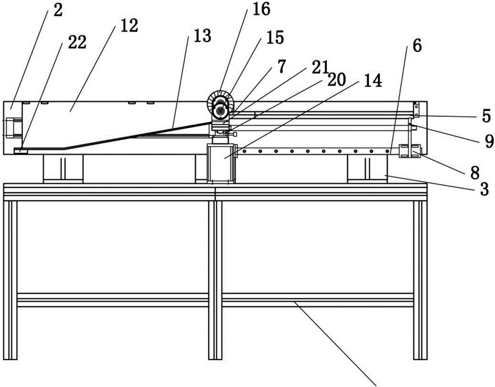
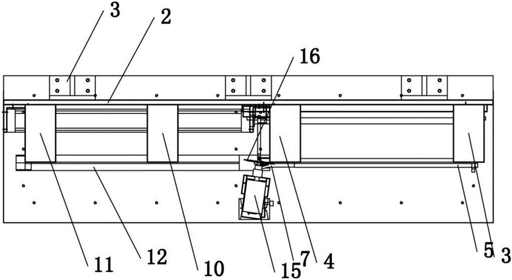
[0021] Such as Figure 1 to Figure 6 The shown automatic deburring machine for piston ring step surface openings includes a frame 1 and a back plate 2, the back plate 2 is arranged on the frame 1 through the mounting bracket 3, the frame 1 is provided with a grinding mechanism, and the back plate 2. There is a feeding mechanism and a receiving mechanism;

[0022] The feeding mechanism comprises a first feeding boom 4, a second feeding boom 5, a tail end support 6, a transmission guide rail 7 and a guiding device 8, the first feeding boom 4 and the second feeding boom 5 are all arranged on the back plate 2, the second feeding boom 4 The other end of the first feeding cantilever 4 is provided with a tail end bracket 6, the other end of the second feeding cantilever 5 is provided with a guide 8, the backboard 2 is also provided with a transmission guide rail 7, and the transmi...


PUM


Abstract

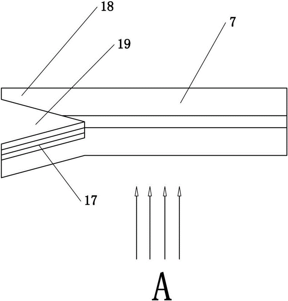
The invention discloses a machine for automatically removing piston-ring tread opening burrs. The machine comprises a machine frame and a back plate. The back plate is arranged on the machine frame through installing supports, both a first feeding cantilever and a second feeding cantilever are arranged on the back plate, a tail-end support is arranged at one end of the first feeding cantilever, a guiding device is arranged at one end of the second feeding cantilever, a pushing air cylinder is arranged on a transmission guiding rail, and a pushing plate is arranged on the pushing air cylinder; a receiving mechanism comprises a first receiving cantilever, a second receiving cantilever and a converse T rod, one ends of the first receiving cantilever and the second receiving cantilever are fixedly connected with the back plate, the converse T rod is connected to the other ends of the first receiving cantilever and the second receiving cantilever, a sliding slope is arranged on the converse T rod, a micro motor is arranged on the machine frame through a supporting base, a shutter wheel for grinding piston-ring burrs is arranged on the micro motor, and the guiding device comprises a guiding protruding block, a guiding slope and a grinding space. The machine is simple and reasonable in structure, the labor strength of employees is reduced, the working efficiency is improved, and the defective rate is reduced.

Description

technical field [0001] The invention relates to a device for automatically removing burrs from workpieces, in particular to a machine for automatically removing burrs from piston ring step surface openings. Background technique [0002] When the trapezoidal piston ring is processing the step surface, burrs are generated on the edge of the step surface and the opening surface, and the burrs are on the opening surface, affecting the opening gap, which does not meet the product requirements. Due to the small free opening of the piston ring, deburring is relatively labor-intensive. The existing method of removing the burr on the opening of the piston ring step surface is: put the whole piston ring on the II-shaped frame, align the opening of the piston ring, first rub the opening surface back and forth with a sand bar manually, and then manually use a copper brush to remove the burr. Brush back and forth along the opening surface; if it is a double-step piston ring, repeat the ...

Claims


Application Information

Patent Timeline
IPC IPC(8): B24B9/04B24B41/00B24B41/02
CPCB24B9/04B24B41/005B24B41/02
Inventor 李标林锐周庆敏李泽斌雷庆友
Owner ANQING TP GOETZE PISTON RING
Learn More