
Method and device for determining conversion pose between radar and camera and electronic equipment

A radar and pose technology, applied in the computer field, can solve problems such as poor robustness, difficulty in application, and poor convergence results, and achieve the effects of low dependence, automation, and stable calibration results

Pending Publication Date: 2021-01-05
BEIJING HORIZON ROBOTICS TECH RES & DEV CO LTD
View PDF0 Cites 13 Cited by
  • Summary
  • Abstract
  • Description
  • Claims
  • Application Information

AI Technical Summary

Problems solved by technology

[0003] However, for the calibration scheme based on the calibration plate, it is easily affected by the camera’s internal parameters and the flatness of the calibration plate, and its robustness is poor; for the calibration scheme based on natural scenes, a higher-precision initial value is required, otherwise the convergence result is poor. However, this is difficult to meet in many practical applications; and the requirements for the external environment are high, and it needs to have obvious, easy to extract, and strong contrast features, which is difficult to apply to most scenarios

Method used


Image

  • Method and device for determining conversion pose between radar and camera and electronic equipment
  • Method and device for determining conversion pose between radar and camera and electronic equipment
  • Method and device for determining conversion pose between radar and camera and electronic equipment

Examples


Embodiment Construction

[0024] Example embodiments according to the present disclosure will be described in detail below with reference to the accompanying drawings. Apparently, the described embodiments are only some of the embodiments of the present disclosure, rather than all the embodiments of the present disclosure, and it should be understood that the present disclosure is not limited by the exemplary embodiments described here.

[0025] It should be noted that relative arrangements of components and steps, numerical expressions and numerical values ​​set forth in these embodiments do not limit the scope of the present disclosure unless specifically stated otherwise.

[0026] Those skilled in the art can understand that terms such as "first" and "second" in the embodiments of the present disclosure are only used to distinguish different steps, devices or modules, etc. necessary logical sequence.

[0027] It should also be understood that in the embodiments of the present disclosure, "plurality...


PUM


Abstract

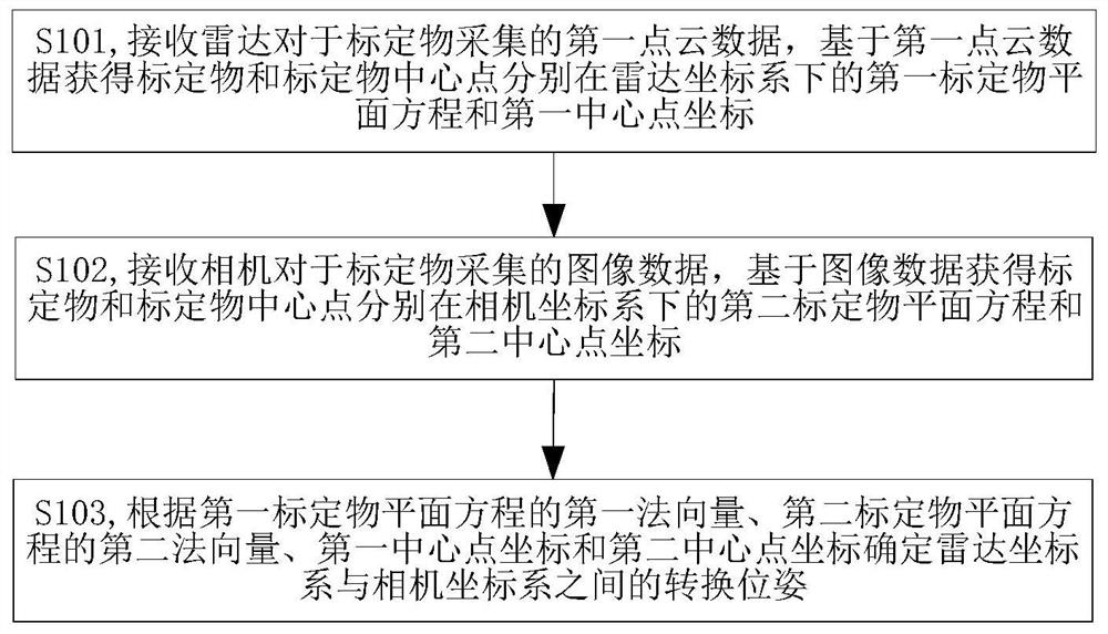
The invention provides a method and a device for determining a conversion pose between radar and a camera, electronic equipment and a storage medium, and relates to the technical field of images. Themethod comprises the steps of acquiring a first calibration object plane equation and a first center point coordinate of a calibration object and a calibration object center point under a radar coordinate system based on first point cloud data acquired by radar; obtaining a second calibration object plane equation and a second center point coordinate of the calibration object and the calibration object center point under the camera coordinate system based on the image data collected by the camera; and determining a conversion pose between the radar coordinate system and the camera coordinate system according to the first normal vector of the first calibration object plane equation, the second normal vector of the second calibration object plane equation, the first center point coordinate and the second center point coordinate. According to the method and the device, the electronic equipment and the storage medium, automation of the calibration process is achieved, manual participationof the calibration process is reduced, the degree of dependence on the calibration board state and the external environment is low, and calibration results are stable.

Description

technical field [0001] The present disclosure relates to the field of computer technology, and in particular to a method and device for determining a conversion pose between a radar and a camera, electronic equipment, and a storage medium. Background technique [0002] Self-driving cars are equipped with various sensors such as radars and cameras. Calibrating the conversion pose relationship between the radar and the camera is a prerequisite for realizing the information fusion of the radar and the camera. By determining the conversion pose between the radar and the camera, the advantages of the two sensors can be complemented and more effective perception information can be obtained. At present, there are usually two schemes for calibrating the conversion pose relationship between radar and camera: calibration schemes based on calibration boards and calibration schemes based on natural scenes. The calibration scheme based on the calibration board usually reconstructs the a...

Claims


Application Information

Patent Timeline
IPC IPC(8): G01S13/86G01S13/89G01S7/41G01S7/40G06T7/73G06T7/80G06T7/10G06K9/62
CPCG01S13/867G01S13/89G01S7/415G01S7/40G01S7/4004G06T7/73G06T7/80G06T7/10G06T2207/10028G06T2207/30252G06F18/23
Inventor 闫明杨德刚
Owner BEIJING HORIZON ROBOTICS TECH RES & DEV CO LTD
Learn More