
Assembly car of conveyor line

A technology for assembling vehicles and conveyor lines, applied in conveyors, mechanical conveyors, transportation and packaging, etc., which can solve problems such as low work efficiency, inconvenient operation, and potential safety hazards.

Inactive Publication Date: 2017-05-10
GUANGZHOU TECH LONG PACKAGING MACHINERY CO LTD
View PDF8 Cites 0 Cited by
  • Summary
  • Abstract
  • Description
  • Claims
  • Application Information

AI Technical Summary

Problems solved by technology

[0002] At present, when assembling products, there are two assembly methods, one is to place the product in situ, place the assembly materials around the product, and assemble the product in situ, the work efficiency of this assembly method is very low; It is to place the product on the flatbed truck, place the flatbed truck on the conveying track, set an assembly station at a certain distance on the conveying track, install a component for each assembly station, and drive the flatbed cart to move along the conveying track to the corresponding position through the power source. After the assembly station, the telescopic rod of the cylinder is stretched out to block the forward movement of the flatbed truck, and the workers carry out the assembly. However, the materials currently assembled are usually transported to the outside of each assembly station according to the principle of convenient transportation, and some parts are assembled. On the inner side of the product, this requires workers to cross the conveying track back and forth to take materials, and then move to the inner side of the conveying track to assemble product components. The work efficiency is also low and the operation is inconvenient. Occasionally, when the control system fails, the flatbed truck will be blocked. At this time, if the worker is crossing the conveyor track, he will be hit by an unobstructed flatbed truck, which poses a certain safety hazard

Method used


Image

  • Assembly car of conveyor line
  • Assembly car of conveyor line
  • Assembly car of conveyor line

Examples


Embodiment Construction

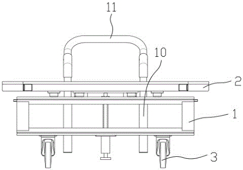
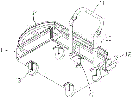
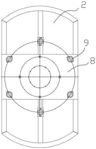
[0011] An assembly vehicle for a conveyor line, such as Figure 1 to Figure 5 As shown, it includes a lower support platform 1 and an upper support platform 2 that can rotate relative to the lower support platform 1. The bottom of the lower support platform 1 is provided with a roller 3 that matches the conveying track, and the bottom surface of the upper support platform 2 is provided with A plurality of positioning grooves, the upper surface of the lower support platform 1 is provided with a plurality of stoppers 13 that match the positioning grooves on the bottom surface of the upper support platform 2, and the stoppers 13 include The spring on the surface, the spring top is connected with the spherical head 4 that matches with the positioning groove, under the natural state of the spring, the spherical head 4 on it is inserted in the positioning groove of the corresponding upper support platform 2 bottom surface, and the lower support platform 1 and the upper support platf...


PUM


Abstract

The invention provides an assembly car of conveyor line. The assembly car comprises a lower support platform and an upper support platform which can rotate relative to the lower support platform; a roller which cooperates with a transfer track is arranged on the bottom of the lower support platform, a variety of locating grooves are arranged on the bottom of the upper support platform, a variety of stoppers which cooperate with the locating grooves on the bottom of the upper support platform are arranged on the upper surface of the lower support platform; the stoppers comprise springs, the springs are arranged on the upper surface of the lower support platform, spherical heads which cooperate with the locating grooves are arranged in connection with the upper parts of the springs; when the springs are under the natural state, the spherical heads on the springs are inserted in the corresponding locating grooves on the bottom of the upper support platform, the lower support platform and the upper support platform are connected into a whole through the roller, a foot-pedal-operated brake is also arranged on the lower support platform. The assembly car of conveyor line helps to conduct operations only on the outer side of the transfer track when assembling goods, which avoids safety risk.

Description

technical field [0001] The invention relates to an assembly trolley for a conveyor line for transporting products to be assembled on a conveyor line. Background technique [0002] At present, when assembling products, there are two assembly methods, one is to place the product in situ, place the assembly materials around the product, and assemble the product in situ, the work efficiency of this assembly method is very low; It is to place the product on the flatbed truck, place the flatbed truck on the conveying track, set an assembly station at a certain distance on the conveying track, install a component for each assembly station, and drive the flatbed cart to move along the conveying track to the corresponding position through the power source. After the assembly station, the telescopic rod of the cylinder is stretched out to block the forward movement of the flatbed truck, and the workers carry out the assembly. However, the materials currently assembled are usually tran...

Claims


Application Information

Patent Timeline
IPC IPC(8): B65G35/00
CPCB65G35/00
Inventor 何文明赵景峰符小玢
Owner GUANGZHOU TECH LONG PACKAGING MACHINERY CO LTD
Learn More