Disc-dividing wire-wrap device capable of automatically unloading wires

A winding device and automatic unloading technology, which is applied in the directions of transportation and packaging, conveying filamentous materials, thin material processing, etc., can solve the problems of material waste on the winding shaft, low winding efficiency, low work efficiency, etc., and improve work efficiency. High efficiency, large winding area and high work efficiency

Inactive Publication Date: 2017-05-10
姜沆
View PDF0 Cites 13 Cited by
  • Summary
  • Abstract
  • Description
  • Claims
  • Application Information

AI Technical Summary

Problems solved by technology

[0002] In the existing wire production industry or the textile industry, it is necessary to carry out winding processing on the produced wire products; the existing winding device has a simple structure and has many disadvantages. One is the winding in the middle of the existing winding device. The spools are all one shaft, resulting in less winding amount per turn and low winding efficiency, and the use of large diameter spools will waste materials and inconvenient installation; the second is that there is no disc processing on the spool , only one wire can be wound on one winding shaft at the same time, and even if the existing winding shaft has sub-disc processing, the size of the sub-disc area cannot be adjusted. It is very inconvenient when thin wires occupying a small space are needed; third, when a large amount of wire is hoarded after winding the winding shaft, it is troublesome to unload the wound wire from the winding shaft, and most of them use The method of manual disassembly has low work efficiency

Method used


Image

  • Disc-dividing wire-wrap device capable of automatically unloading wires
  • Disc-dividing wire-wrap device capable of automatically unloading wires
  • Disc-dividing wire-wrap device capable of automatically unloading wires

Examples


Embodiment Construction

[0017] The present invention will be further illustrated below in conjunction with the accompanying drawings and specific embodiments. This embodiment is implemented on the premise of the technical solution of the present invention. It should be understood that these embodiments are only used to illustrate the present invention and are not intended to limit the scope of the present invention.

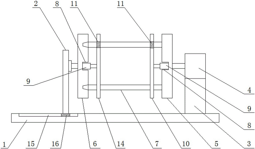
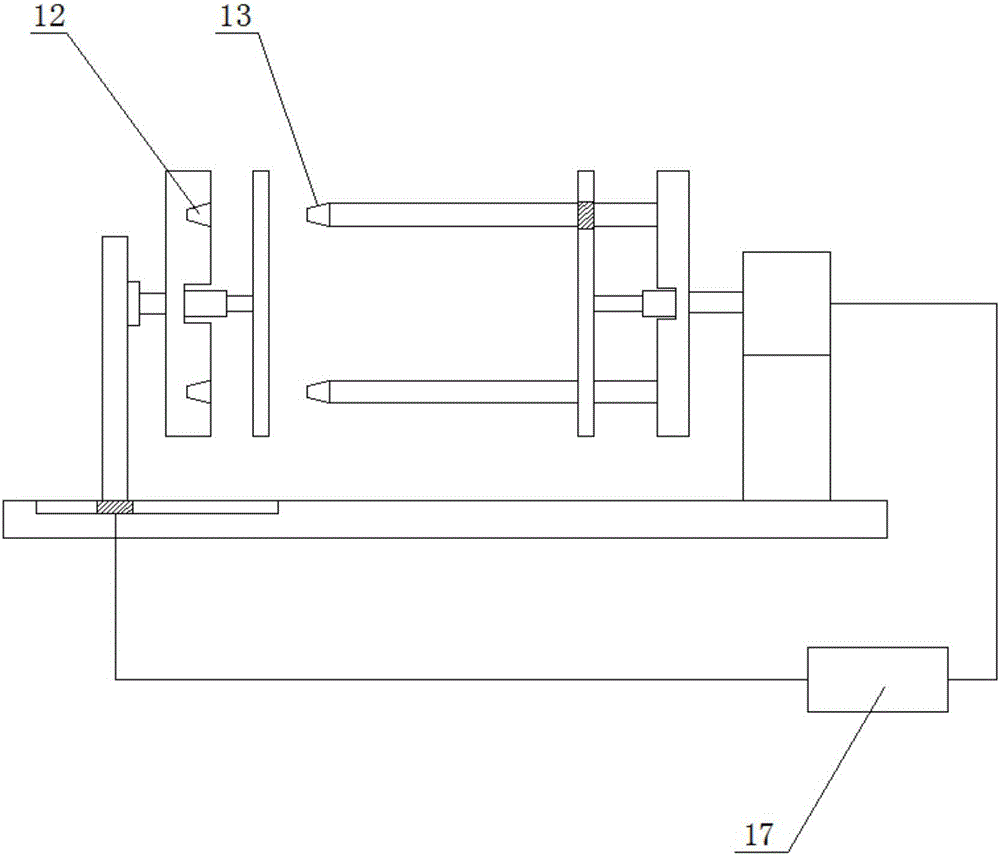
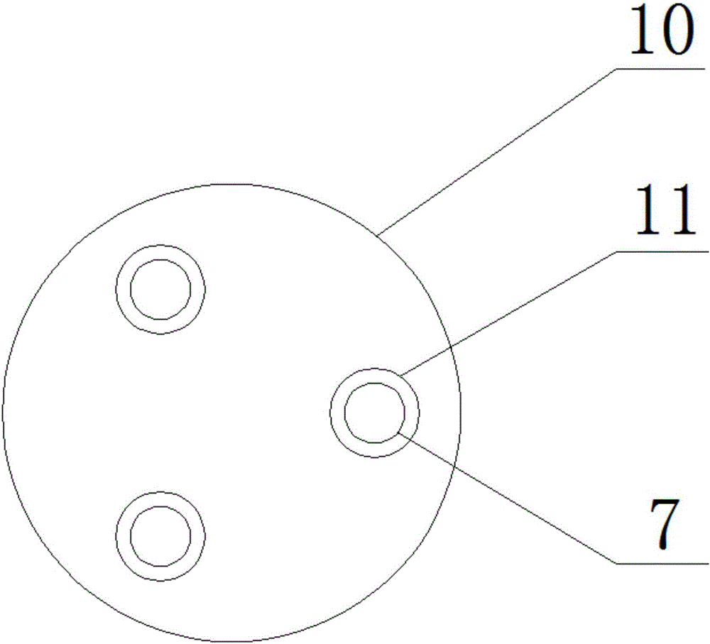
[0018] like figure 1 , figure 2 and image 3 As shown, a split coil winding device that can automatically unload the wire includes a base 1; the left and right sides of the base 1 are respectively equipped with a left side plate 2 and a right side plate 3; There is a servo motor 4; the servo motor 4 is placed horizontally, and the screw rod of the servo motor is also placed horizontally, and an active winding reel 5 is installed on the end of the screw rod; the left side plate 2 is equipped with an active winding coil through a bearing structure. The reel 5 cooperates with the driven...


PUM


Abstract

The invention discloses a disc-dividing wire-wrap device capable of automatically unloading wires. The disc-dividing wire-wrap device comprises a base; a left side plate and a right side plate are installed on the left side and the right side of the base correspondingly, a horizontally-installed servo motor is installed on the right side plate, and a threaded rod of the servo motor is horizontally installed; and a driving wire-wrap disc is installed at the end of the threaded rod. According to the disc-dividing wire-wrap device capable of automatically unloading the wires, a disc-dividing plate has the effects of dividing discs and unloading the wires on a first wire-wrap area, and when a driven wire-wrap disc moves towards the left side, the disc-dividing plate moves towards the left side at the same time, so that the wires on the first wire-wrap area are pushed, the disc-dividing plate moves all the time till breaking away from a wire-wrap shaft, and then the wires on the first wire-wrap area are unloaded by the disc-dividing plate; and the wires on a second wire-wrap area can be unloaded by a push plate. Thus, the device has the effects of disc dividing and wire unloading.

Description

technical field [0001] The invention relates to a wire winding device, in particular to a coil winding device which can automatically unload the wire. Background technique [0002] In the existing wire production industry or the textile industry, it is necessary to carry out winding processing on the produced wire products; the existing winding device has a simple structure and has many disadvantages. One is the winding in the middle of the existing winding device. The spools are all one shaft, resulting in less winding amount per turn and low winding efficiency, and the use of large diameter spools will waste materials and inconvenient installation; the second is that there is no disc processing on the spool , only one wire can be wound on one winding shaft at the same time, and even if the existing winding shaft has sub-disc processing, the size of the sub-disc area cannot be adjusted. It is very inconvenient when thin wires occupying a small space are needed; third, when...

Claims


Application Information

Patent Timeline
Patent Type & Authority Applications(China)
IPC IPC(8): B65H75/22B65H75/14B65H75/24B65H67/04
CPCB65H75/22B65H67/0411B65H75/14B65H75/24
Inventor 姜沆
Owner 姜沆
Why Eureka
Try Eureka