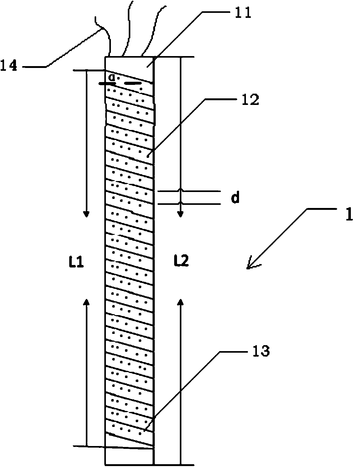
[0054] The core idea of the present invention is: put a temperature-probe that can be heated into the interface between the silicone rubber sheath of the composite insulator and the epoxy resin core rod, and at the same time use an infrared temperature measuring device to measure the temperature outside, thereby obtaining the composite The relationship between the temperature rise on the outer surface of the insulator and the actual temperature rise inside the insulator.
[0055] In order to make the objectives, technical solutions, and advantages of the present invention clearer, the following further describes the present invention in detail with reference to the accompanying drawings and embodiments. It should be understood that the specific embodiments described here are only used to explain the present invention, but not to limit the present invention.
[0056] See figure 1 As shown, the temperature measuring probe 1 capable of raising the temperature in this embodiment mainly includes a thermocouple 11, an insulating tape 12, a manganese copper wire 13 and a wire 14.
[0057] Among them, the insulating tape 12 is pasted on the surface of the thermocouple 11 through the mixed glue; the manganese copper wire 13 is tightly single-layered and wound on the insulating tape 12 at intervals; the wire 14 has three wires, two electric heating wire power supply wires and one The thermocouple transmission wire, two electric heating wire power supply wires are respectively connected to different ends of the manganese copper wire 13, and the thermocouple transmission wire is connected to the thermocouple 11.
[0058] See figure 2 As shown, the manufacturing method of the temperature measuring probe 1 capable of raising temperature in this embodiment is specifically as follows:
[0059] 201. Choose a suitable thermocouple 11, whose temperature measurement range should be greater than 300℃, and the size should be as small as possible, recommended: 30*5*2.5mm.
[0060] 202. Coat the surface of the thermocouple 11 with mixed glue, and reversely stick the insulating tape 12 on the surface of the thermocouple 11 so that the sticky side faces outward.
[0061] 203. The manganese copper wire 13 is selected, and the insulating tape 12 on the thermocouple 11 is tightly wound in a single layer.
[0062] On the one hand, since the heating power is proportional to the winding length of the manganese copper wire, in order to provide sufficient heating power at a small current, the winding length of the manganese copper wire should be long enough, and the manganese copper wire should be as dense as possible Winding, and the winding inclination should be small. On the other hand, in order to ensure mutual insulation, the manganese copper wires should not touch each other, and the manganese copper wires must be wound in a single layer, which limits the maximum possible winding length of the manganese copper wires. At the same time, in order to make the temperature measurement result of the probe as close as possible to the actual temperature of the manganese-copper wire, the area of the thermocouple wrapped by the manganese-copper wire should be as large as possible. Therefore, in this implementation, the following method is recommended for winding. The temperature of the manganese-copper wire and the measured temperature of the probe obtained by this winding method are within 250°C, and the error is less than ±0.5°C: choose an enameled bag with a diameter of 0.07mm The manganese copper wire 13 (about 120Ω/m) is tightly wound in a single layer on the insulating tape 12 on the thermocouple 11. When winding, the manganese copper wire 13 cannot overlap each other, and the distance d between the two rows of manganese copper wire 13 is not It should exceed 0.5mm; in addition, on the thermocouple 11, the winding length of the manganese copper wire 13 should be greater than 80% of the total length of the thermocouple 11 (L1/L2>0.8), and the winding inclination α should be less than 30°.
[0063] 204. Use an electric soldering iron to weld the upper and lower end joints of the manganese copper wire 13 with the wire.
[0064] The working principle of the above-mentioned temperature-rising temperature measuring probe 1 is that a DC power supply is used to apply a voltage to both ends of the manganese-copper wire 13. Under the action of the ohmic effect, the manganese-copper wire 13 will generate heat. And in close contact with it, the thermocouple 11 can be used to read the actual temperature of the manganese-copper wire 13, and due to the heating of the manganese-copper wire 13, the overall temperature of the temperature probe 1 will also rise, which is the internal part of the thermal convection test. Defects provide a source of heat.
[0065] See image 3 In this embodiment, the thermal convection test system of the composite insulator 0 with artificial defects includes: a temperature-probe that can increase temperature 1, a constant voltage power supply 2, an ammeter 3, a temperature display table 4, and an infrared temperature measuring device 5.
[0066] Among them, the temperature probe 1 that can be heated is fixed and buried in the composite insulator 0 to detect the temperature of the internal defects of the composite insulator 0.
[0067] Constant voltage power supply 2, one end of which is connected to a heating wire power supply wire of temperature measuring probe 1 through ammeter 3, and the other end is directly connected to another heating wire power supply wire of temperature measuring probe 1, which is used to use a DC constant voltage source as The resistive defect of composite insulator 0 supplies power.
[0068] The ammeter 3 is connected between the constant voltage power supply 2 and a heating wire power supply wire of the temperature measuring probe 1 to display the current magnitude in real time.
[0069] The temperature display table 4 is connected to the thermocouple transmission wire of the temperature measuring probe 1 to display the internal temperature of the composite insulator 0 detected by the temperature measuring probe 1 in real time.
[0070] The infrared temperature measuring device 5 is used for real-time measurement of the temperature outside the composite insulator 0.
[0071] See Figure 4 As shown, the method of applying the above-mentioned system to conduct a thermal convection test in this embodiment is:
[0072] 401. The temperature measuring probe 1 that can be heated is fixed and buried in a corresponding position inside the composite insulator 0, that is, on the interface between the silicone rubber sheath and the epoxy resin core rod.
[0073] 402. Use constant voltage power supply 2 to use DC constant voltage source to supply power to the resistive defects of composite insulator 0; in the process of power supply, use temperature measuring probe 1 located inside to detect the internal temperature of composite insulator 0 in real time and record different currents At the same time, use the infrared temperature measuring device 5 to photograph the surface temperature distribution of the composite insulator 0 and record it.
[0074] 403. Record the current temperature and relative humidity of the laboratory during each measurement, and record the current flowing through the composite insulator 0 and the time to stabilize, which should not be less than 90 minutes.
[0075] 404. After sorting and analyzing the recorded data, the relationship between the outer surface temperature rise of the composite insulator 0 containing artificial defects and the actual inner temperature rise can be obtained.
[0076] In the above test, the relationship between the position of the heating defect and the external infrared result needs to be studied. Therefore, the temperature measuring probe 1 needs to be accurately embedded in the corresponding position inside the composite insulator 0. However, due to the injection process, the cavity atmospheric pressure can reach 100 atmospheres, and during the subsequent vulcanization process, the internal temperature of the composite insulator 0 can reach 150-160°C. Due to the high internal air pressure, the impact on the sample during injection is relatively large, and for the accuracy of the test and research results, the material similar to the composite insulator should be used for fixing as much as possible, and the temperature during injection is relatively high. The glue will volatilize and the viscosity will decrease. At the same time, because the probe is small and connected to 3 thin wires, the connection part is relatively fragile. It is necessary to ensure that the connection of each part is not damaged by the insulator injection process under the condition of ensuring insulation. Therefore, the temperature measuring probe 1 needs to be used Special fixing method.
[0077] See Figure 5 In this embodiment, the method for fixing the temperature probe 1 at the corresponding position inside the composite insulator 0 is:
[0078] 501. After the mandrel is ground, a groove is made on the surface of the mandrel. The groove width is 6mm and the depth is 5mm. The groove is opened from one end of the mandrel to the required position for the experiment. The position is determined according to different test requirements. It is recommended to be buried in Under the third umbrella skirt of the composite insulator sheath.
[0079] 502. Put the temperature measuring probe 1 into the groove on the surface of the mandrel, apply a small amount of epoxy resin to the buried position to fix the temperature measuring probe 1, and make the surface of the temperature measuring probe 1 just expose the notch to ensure the injection molding The rear temperature measuring probe 1 is located on the interface between the core rod and the sheath.
[0080] 503. After 12 hours, after the epoxy resin is cured, fill in a large amount of epoxy resin to fill the entire tank. Note that when injecting epoxy resin, place the heating wire power supply wires of the temperature measuring probe 1 on both sides of the bottom of the groove and make them not contact each other as much as possible. The thermocouple transmission wires are placed in the middle of the bottom of the groove.
[0081] 504. Use an air dryer to dry at 130°C for at least 2 hours.
[0082] 505. Use a knife to carefully scrape off the cured epoxy resin overflowing the tank, and completely expose the manganese copper wire 13 to the air.
[0083] 506. Put the core rod into the mold and perform injection to form a silicone rubber sheath. At this time, the structure of the core rod after the temperature probe 1 is fixed is as follows Image 6 Shown.
[0084] The advantages of using the above temperature measuring probe and fixing method are:
[0085] 1) The temperature measurement probe provided in this embodiment can ensure the minimum volume on the basis of ensuring the temperature rise and temperature measurement functions. The use of a small probe can firstly restore the actual composite insulators with heating defects on the actual circuit, avoiding the thickness of the sheath being too thin or the effective diameter of the core rod being reduced due to the excessively large probe, which affects the accuracy of the test results, and the small probe It can also reduce the chance of damage to the sheath during injection.
[0086] 2) Provide sufficient connection strength. The temperature and air pressure during injection are high (100 atmospheres, above 150°C). If the connection method is not good, it is easy to cause the internal wire to be broken, which will cause the entire sample to fail. The preparation experience of 15 samples shows that the use of this fixing method can effectively avoid internal disconnection, and after a month of thermal convection test, the connection performance is still good.
[0087] 3) Provide sufficient insulation strength. This fixing method effectively solves the problem of wiring the small probe on the basis of ensuring the connection strength, and the sample can still ensure sufficient insulation strength under the harsh conditions of injection. The preparation of 15 samples shows that using this fixing method can effectively avoid internal short circuits, and after one month of thermal convection test, the insulation performance is still good.
[0088] 4) It can provide sufficient heating power for the thermal convection test. The existing results show that when heating occurs inside the composite insulator, the overall temperature of the defect can reach more than 200°C, thereby causing damage to the silicone rubber material. Therefore, during the thermal convection test, the defect temperature should reach 200 degrees Celsius. This fixing method can obtain 200°C high-temperature heating defects.
[0089] 5) The temperature measurement is accurate. Using this fixing method, the manganese-copper wire is wound tightly in a single layer on the surface of the thermocouple. At the same time, the winding area is large. Therefore, in the final thermal equilibrium state, the temperature of the manganese-copper wire is measured with the thermocouple. The temperature error is very small, within 200℃, the error is less than 0.5℃. This can bring great convenience to further analysis of experimental results.
[0090] 6) The operation is simple and easy, and the cost is low. At present, there is no heating temperature measuring probe for thermal convection test of composite insulators on the market. Using this fixing method to make and install the probe, the performance parameters fully meet the test requirements, and the cost is low, the operation is simple, and no special training is required. In addition, the fixing method and the embedding method do not affect the overall process of composite insulator injection production, and will not affect the production plans of related manufacturers.
[0091] 7) The test conditions are low, and the samples prepared by this fixing method only need 18V DC power when conducting thermal convection tests. The internal heating temperature of the defect can reach 200℃, which can be tested in most laboratories.
[0092] The above are only the preferred embodiments of the present invention and are not intended to limit the present invention. Any modification, equivalent replacement and improvement made within the spirit and principle of the present invention shall be included in the protection of the present invention. Within range.