Multi-cable compounded damping cable

A composite damping and auxiliary cable technology, applied in the field of structural vibration reduction, can solve the problems of reducing the axial rigidity, increasing the tension of the main cable, and reducing the lateral rigidity, so as to reduce the gravitational sag, reduce the lateral deformation, reduce the The effect of vibration

Inactive Publication Date: 2017-05-10
HUNAN UNIV OF SCI & TECH
View PDF5 Cites 5 Cited by
  • Summary
  • Abstract
  • Description
  • Claims
  • Application Information

AI Technical Summary

Problems solved by technology

This method cannot be applied to achieve vibration reduction between two structures that are far apart
[0003] The double-cable composite damping cable can achieve vibration reduction between two structures that are far apart, but it has the following disadvantages: (1) The main cable has a large axial stiffness, because the auxiliary cable sags in the vertical plane, so The vertical stiffness of the main cable and the auxiliary cable is relatively large, while the lateral stiffness is very small, and a large lateral deformation will occur under the action of the transverse wind, resulting in a significant increase in the tension of the main cable, resulting in a large deformation of the structure
(2) When the structure vibrates, a periodically changing tensile force will be generated in the axial direction of the main cable and the auxiliary cable. When the change frequency of the tension force is consistent with the natural frequency of the main cable or auxiliary cable, it will cause a large Vibration, which adversely affects structural vibration damping
(3) The damper is installed near the lower anchorage end, and the stiffness of the spring connected in parallel with the damper is smaller than the axial stiffness of the main cable. When the structure vibrates, the main deformation of the main cable occurs at the parallel spring of the damper. The deformation of the auxiliary cable is basically uniform along the axis, resulting in different moving distances between the cross section of the main cable and the cross section of the auxiliary cable. Under the restraint of suspenders of different lengths, the main cable will undergo large lateral deformation, which will reduce its axial stiffness and affect the reduction. vibration effect

Method used


Image

  • Multi-cable compounded damping cable
  • Multi-cable compounded damping cable
  • Multi-cable compounded damping cable

Examples


Embodiment Construction

[0027] The present invention will be further described in detail below in conjunction with the accompanying drawings and embodiments.

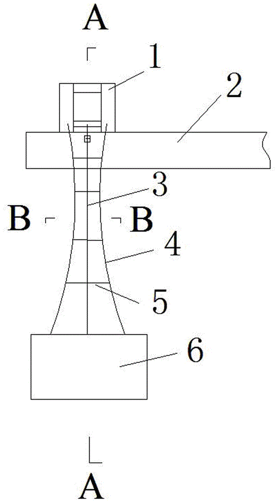
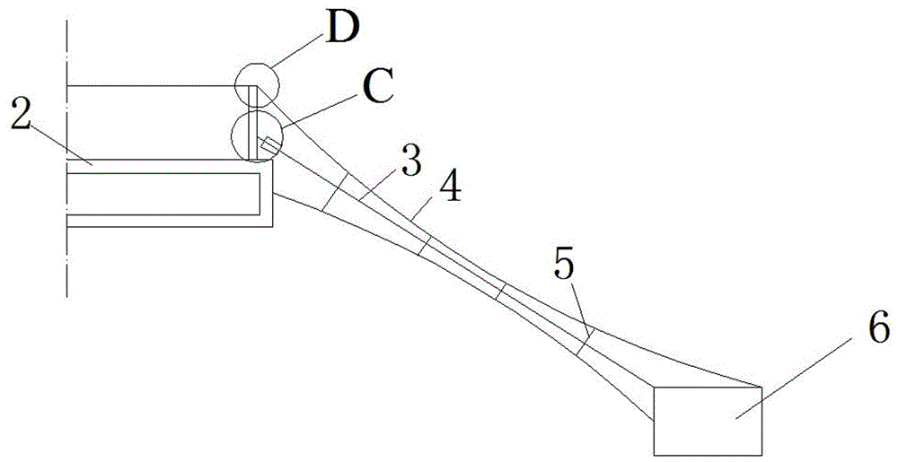
[0028] see figure 1 , figure 2 , the present embodiment takes bridge cantilever construction as an example, install main cable 3 and auxiliary cable 4 between the bridge under cantilever construction and the ground, auxiliary cable 4 is distributed around main cable 3; the lower ends of main cable 3 and auxiliary cable 4 are fixed on the ground The upper end of the main cable 3 is connected to the upper anchorage column 1 fixed on the structure 2 (main beam of the bridge) through the main cable vibration damping device C, and the upper end of the auxiliary cable 4 is connected through the auxiliary cable vibration damping device D It is connected with the upper anchor column 1 fixed on the structure; a suspender 5 is arranged between the main cable 3 and the auxiliary cables 4 and between the auxiliary cables 4 .

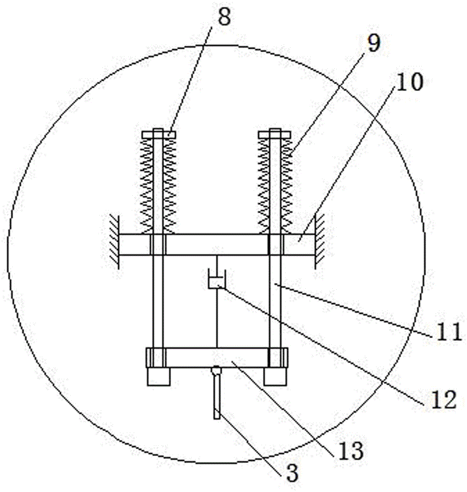
[0029] see image 3 , th...


PUM


Abstract

The invention discloses a multi-cable compounded damping cable. The technical key point lies in that the multi-cable compounded damping cable comprises a main cable and at least one secondary cable distributed around the main cable, and the at least one secondary cable is located on the upper portion of the main cable. The lower ends of the main cable and the secondary cables are connected with a concrete anchor fixed to the ground. The upper end of the main cable is connected with an upper anchoring end stand column fixedly connected with a structure through a main cable shock absorption device. The upper ends of the secondary cables are connected with the upper anchoring end stand column fixedly connected with the structure through a secondary cable shock absorption device. Hanging rods are arranged between the main cable and each secondary cable as well as between the secondary cables. According to the multi-cable compounded damping cable, the multi-cable compounded damping cable can be installed between two structures which are at a long distance and move relatively, and has the energy dissipation and shock absorption effects basically equal to those of a damper installed between two structures very close to each other.

Description

technical field [0001] The invention belongs to the technical field of structural vibration reduction, and in particular relates to a multi-cable composite damping cable. Background technique [0002] Viscous dampers are widely used in structural wind and earthquake resistance because of their strong energy dissipation capacity, reliable operation, good robustness, convenient installation and low cost. However, when the viscous damper performs energy dissipation and vibration reduction on structural vibration, it needs to be installed at a point near the structure that has relative motion, and the piston rod of the damper and the cylinder are driven to reciprocate through the relative motion between the structure and the point. The relative motion dissipates energy, thereby reducing the vibration of the structure. Under the action of earthquake or wind, super high-rise buildings will experience relatively large lateral vibration (or vibration). The existing vibration reduct...

Claims


Application Information

Patent Timeline
Patent Type & Authority Applications(China)
IPC IPC(8): E01D19/16
CPCE01D19/16
Inventor 禹见达张湘琦于浩王修勇孙洪鑫禹蒲阳
Owner HUNAN UNIV OF SCI & TECH
Why Eureka
Try Eureka