
Piling machine for containing river dike break

A technology for pile drivers and river dams, which is applied to sheet pile walls, buildings, infrastructure projects, etc., can solve the problems of prolonged containment work, great effort, and difficulties in containment, and achieves faster embedding speed and simpler production. , the effect of speeding up the rescue

Active Publication Date: 2017-05-10
李沛
View PDF9 Cites 0 Cited by
  • Summary
  • Abstract
  • Description
  • Claims
  • Application Information

AI Technical Summary

Problems solved by technology

[0002] Every summer, large and small river dams often break, which brings great losses to people’s lives and property. If the breakage begins at the beginning, the breach will be blocked by artificial means immediately, so that there will be no large-scale collapse and It is necessary to race against time to block quickly to be effective. The current containment method is to manually drive steel pipes into the crevasse of the dam. After the first one is laid, the second one is driven in after a certain distance, and then it is beaten to the entire breach area. , and then fill it with sandbags and other things until the river is completely blocked. What I want to talk about here is that when hitting the steel pipe, one person needs to hold the steel pipe with both hands, and another person next to him uses a big hammer to hit the end of the steel pipe. It takes a long time and a lot of effort to drive the steel pipe into the ideal size, which greatly delays the rescue time, prolongs the containment work, and causes the difficulty of containment

Method used


Image

  • Piling machine for containing river dike break
  • Piling machine for containing river dike break
  • Piling machine for containing river dike break

Examples


Embodiment Construction

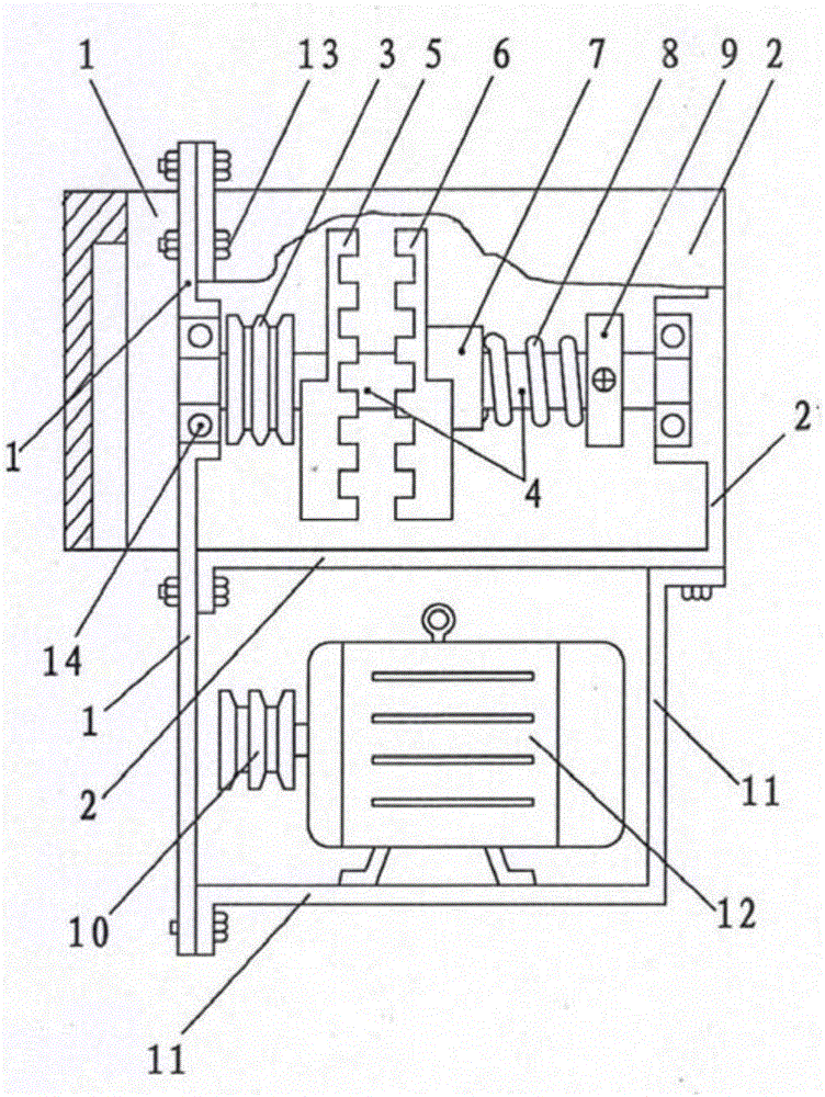
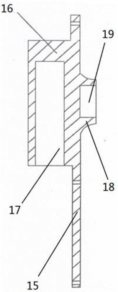
[0019] Such as figure 1 , a pile driver for containment of river dam collapse, which includes a special-shaped hammer 1, a support frame 2, a main shaft pulley 3, a main shaft 4, an active eccentric wheel 5, a passive eccentric wheel 6, a special-shaped sleeve 7, a spring 8, and a spring collar 9 , motor pulley 10, motor support base 11, motor 12, fastening bolt 13 and bearing 14, such as figure 2 and image 3 The middle part of the special-shaped hammer 1 is an elongated flat plate structure 15, and one side of the flat plate structure 15 is provided with an elongated hammer head 16 integrally formed with the flat plate structure 15, and a hammer head 16 is opened from the lower end. An impermeable mounting hole 17, the other side of the flat plate structure 15 protrudes and is provided with a cylindrical boss 18 integrally formed with the flat plate structure 15, and the middle part of the cylindrical boss 18 is provided with a circular recess that is assembled and connect...


PUM


Abstract

The invention relates to a piling machine for containing river dike break. The piling machine comprises a special-shaped hammer, a supporting frame, a main shaft belt pulley, a main shaft, a driving eccentric wheel, a driven eccentric wheel, a special-shaped sleeve, a spring, a spring clamping ring, a motor belt pulley, a motor supporting seat and a motor. A flat plate structure of the special-shaped hammer is connected with an arc-shaped flange disc of the supporting frame in a manner that bolts pass through connecting holes. The two ends of the main shaft are mounted in a circular recess and a circular groove through bearings. The main shaft belt pulley, the driving eccentric wheel, the driven eccentric wheel, the special-shaped sleeve, the spring and the spring clamping ring are mounted on the main shaft. The spring pushes the special-shaped sleeve, so that the driven eccentric wheel and the driving eccentric wheel are pressed together in an ejected manner. The motor supporting seat and the special-shaped hammer are connected with the supporting frame. The motor belt pulley is mounted on a rotating shaft of the motor. The main shaft belt pulley is in transmission connection with the motor belt pulley through a belt. According to the piling machine, a vibrating mechanism is combined with a piling mechanism; the piling machine is simple in structure, compact in size and convenient to operate; and the speed of rescue and relief work is greatly increased.

Description

technical field [0001] The invention belongs to the technical field of small-scale machinery manufacturing, and in particular relates to a pile driver for containment of river dam bursts. Background technique [0002] Every summer, large and small river dams often break, which brings great losses to people’s lives and property. If the breakage begins at the beginning, the breach will be blocked by artificial means immediately, so that there will be no large-scale collapse and It is necessary to race against time to block quickly to be effective. The current containment method is to manually drive steel pipes into the crevasse of the dam. After the first one is laid, the second one is driven in after a certain distance, and then it is beaten to the entire breach area. , and then fill it with sandbags and other things until the river is completely blocked. What I want to talk about here is that when hitting the steel pipe, one person needs to hold the steel pipe with both hand...

Claims


Application Information

Patent Timeline
IPC IPC(8): E02D7/18
CPCE02D7/18
Inventor 李沛
Owner 李沛
Learn More