An Intensive Locking Multi-mode Hydraulic Variable Valve Drive System

A drive system, locking technology, applied in the direction of engine components, machines/engines, non-mechanically actuated valves, etc., to achieve the effect of improving power

Inactive Publication Date: 2018-12-25
DALIAN UNIV OF TECH
View PDF8 Cites 0 Cited by
  • Summary
  • Abstract
  • Description
  • Claims
  • Application Information

AI Technical Summary

Problems solved by technology

At present, there is no variable valve drive system that can meet the above requirements at the same time, so the development of a multi-mode variable valve drive system is imminent

Method used


Image

  • An Intensive Locking Multi-mode Hydraulic Variable Valve Drive System
  • An Intensive Locking Multi-mode Hydraulic Variable Valve Drive System
  • An Intensive Locking Multi-mode Hydraulic Variable Valve Drive System

Examples


Embodiment Construction

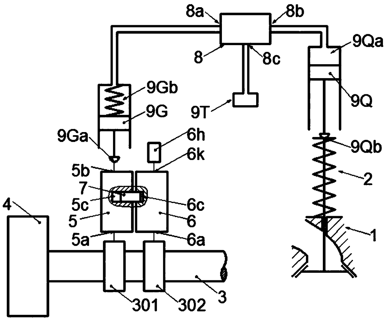
[0040] The invention relates to an intensive locking multi-mode hydraulic variable valve drive system. It includes valve driving mechanism 2, camshaft phase adjustment mechanism 4 on camshaft 3, camshaft 3, mode transmission mechanism 5, mode selection mechanism 6, mode switching mechanism 7, valve control mechanism 8, plunger oil supply 9G, piston driver 9Q and oil reservoir 9T. figure 1 It is a schematic diagram of an intensive lock-type multi-mode hydraulic variable valve drive system with double-cam drive, double-input, single-output, single-switching, single-valve operation, and single-regulation. The camshaft 3 is provided with a first cam 301 and a second cam 302 . The first cam 301 has one protrusion, and the second cam 302 has one protrusion or two protrusions. The projection of the second cam 302 having one projection has the same profile as the projection of the first cam 301, and the phase difference is 180° of camshaft rotation angle. The profiles of the two pr...


PUM


Abstract

An intensive locking multi-mode hydraulic variable valve driving system belongs to the field of engine valve driving. It mainly includes camshaft, mode transmission mechanism, mode alternative mechanism, mode switching mechanism, camshaft phase adjustment mechanism, plunger type oil supply device, piston driver, valve control mechanism, etc. The mode switching mechanism is used in conjunction with the camshaft phase adjustment mechanism to realize the conversion between engine two-stroke driving mode, four-stroke driving mode, two-stroke braking mode, four-stroke braking mode and other modes, and further through the valve control mechanism Used together, it finally meets the requirements of the engine for optimal ventilation under different working conditions, and achieves the purpose of comprehensively improving engine power, fuel economy, emissions and braking safety. The invention has a simple and compact structure and is easy to arrange, and provides users with different schemes for flexibility, reliability, cost and other requirements of variable valves for them to choose.

Description

technical field [0001] The invention relates to an intensive locking multi-mode hydraulic variable valve drive system, which belongs to the field of engine valve drive. Background technique [0002] With the increasingly serious energy and environmental issues, and people's focus on driving and safety of vehicles, future engines need to comprehensively consider power, economy, emissions and safety on the premise of meeting emission standards. This requires optimizing engine performance over the full range of driving and braking conditions. At present, technologies such as variable valve, variable stroke number, cylinder deactivation, auxiliary braking, new combustion mode, variable compression ratio, variable EGR and other technologies that have attracted much attention only affect the performance of the engine in a small range of operating conditions. Make improvements. For example, the existing variable valve technology is only applied to the driving condition of the fix...

Claims


Application Information

Patent Timeline
Patent Type & Authority Patents(China)
IPC IPC(8): F01L9/02F01L9/14
CPCF01L9/12
Inventor 崔靖晨隆武强田江平田华王阳刘威杨添淏
Owner DALIAN UNIV OF TECH
Why Eureka
Try Eureka