
Bridge pipeline supporting structure

A pipeline support and bridge technology, applied in the direction of pipeline supports, pipes/pipe joints/pipe fittings, devices to prevent contact with live contacts, etc., can solve the problems of pipeline maintenance or moving fixed positions, difficult to remove, etc., to achieve convenient and automatic Controlled unlocking, avoiding the risk of electric shock, and convenient disassembly and assembly

Active Publication Date: 2017-05-10
江苏创安结构设计事务所有限公司
View PDF6 Cites 7 Cited by
  • Summary
  • Abstract
  • Description
  • Claims
  • Application Information

AI Technical Summary

Problems solved by technology

[0002] We can often see large and small plastic pipes on some bridges. Some of these pipes are used for drainage, and some are used for wiring. Due to the long length of plastic pipes and high gravity, it is necessary to set up support structures on the bridge wall to support them. , to prevent sagging, in the prior art, the supporting frame is generally set on the bridge wall to achieve the supporting purpose, but since the supporting frame is fixed by a spiral structure, it is difficult to remove it after it is fixed, for In the future, it will bring great inconvenience to overhaul or move the fixed position of the pipeline. At the same time, since the support frame is installed on the bottom side of the bridge, it should be a warning to the passing ships when the water level is high or the visibility is low at night, which is also to ensure the safety of the ships. Necessary measures for traffic and bridge safety

Method used


Image

  • Bridge pipeline supporting structure
  • Bridge pipeline supporting structure
  • Bridge pipeline supporting structure

Examples


Embodiment Construction

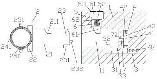
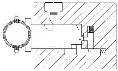
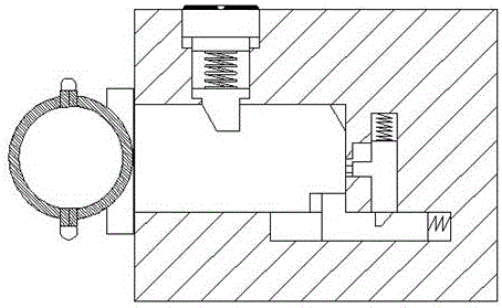
[0023] like Figure 1-Figure 5 As shown, a bridge pipeline support structure of the present invention includes a support base 1 and a support member 2 cooperating with the support base 1, and the support member 2 is composed of a support ring 241, a fastening plate 22 and a support rod 21. , the support ring 241 is fixedly arranged on the left side of the fastening plate 22, and the ring body of the support ring 241 is symmetrically arranged with two outwardly extending ends 250, and the ends 250 are provided with There is a warning light 251, and the right side of the fastening plate 22 is fixedly connected with a support rod 21, and the end surface of the support rod 21 away from the fastening plate 22 is provided with a beveled portion 23, and the beveled portion 23 is connected to the The top of the support rod 21 between the fastening plates 22 is provided with a left insertion slot 211, and the support seat 1 is provided with a plug-in compartment 11 for cooperating with...


PUM


Abstract

The invention discloses a bridge pipeline supporting structure. The bridge pipeline supporting structure comprises a supporting base and a supporting piece connected with the supporting base in a matched manner; the supporting piece is composed of a supporting ring, a fastening plate and a supporting rod; the supporting ring is fixedly arranged on the left side of the fastening plate; two end portions extending outwards are symmetrically arranged in the ring body of the supporting ring in the up-down direction; the end portions are provided with caution lamps; the supporting rod is fixedly connected to the right side of the fastening plate; the end face of the side, backing to the fastening plate, of the supporting rod is provided with an inclined angle part; a left inserting connection groove is formed in the top end of the portion, between the inclined angle part and the fastening plate, of the supporting rod; an inserting connection bin used for being connected with the supporting rod in a matched manner is arranged in the supporting base; a locking groove is formed in the portion, above the inserting connection bin, of the supporting base; an internal thread hole is formed in the top end of the locking groove in a communicated manner; a left inserting connection block stretching into the inserting connection bin is arranged in the locking groove; a first tension spring is arranged at the top end of the left inserting connection block; and a first sliding groove is vertically formed in the portion, on the right side of the inserting connection bin, of the supporting base in an extending manner.

Description

technical field [0001] The invention relates to the technical field of bridge pipe support, in particular to a bridge pipe support structure. Background technique [0002] We can often see large and small plastic pipes on some bridges. Some of these pipes are used for drainage, and some are used for wiring. Due to the long length of plastic pipes and high gravity, it is necessary to set up support structures on the bridge wall to support them. , to prevent sagging, in the prior art, the supporting frame is generally set on the bridge wall to achieve the supporting purpose, but since the supporting frame is fixed by a spiral structure, it is difficult to remove it after it is fixed, for In the future, it will bring great inconvenience to overhaul or move the fixed position of the pipeline. At the same time, since the support frame is installed on the bottom side of the bridge, it should be a warning to the passing ships when the water level is high or the visibility is low at...

Claims


Application Information

Patent Timeline
IPC IPC(8): F16L3/10H01R13/44
CPCF16L3/10H01R13/44
Inventor 朱海斌
Owner 江苏创安结构设计事务所有限公司
Learn More