
Diagonal axis type dynamic weight measurement system and diagonal axis type dynamic weight measurement method

A diagonal axis and dynamic technology, applied in the direction of measuring devices, weighing equipment testing/calibration, instruments, etc., can solve the problems of relatively high accuracy of weighing measurement and the difficulty of dynamic weighing system to meet the requirements, so as to achieve the effect of improving accuracy

Inactive Publication Date: 2017-05-10
辉因科技(北京)有限公司
View PDF7 Cites 1 Cited by
  • Summary
  • Abstract
  • Description
  • Claims
  • Application Information

AI Technical Summary

Problems solved by technology

These fields have relatively high requirements for weighing accuracy, and the traditional dynamic weighing system is difficult to meet the requirements

Method used


Image

  • Diagonal axis type dynamic weight measurement system and diagonal axis type dynamic weight measurement method
  • Diagonal axis type dynamic weight measurement system and diagonal axis type dynamic weight measurement method
  • Diagonal axis type dynamic weight measurement system and diagonal axis type dynamic weight measurement method

Examples


Embodiment 1

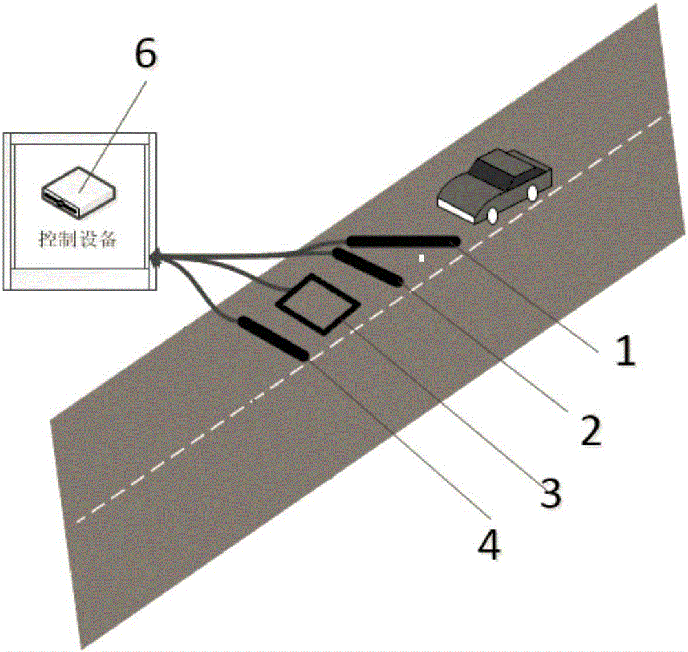
[0021] see figure 1 It shows that the present invention relates to a dynamic weighing system, especially a 1-composition Z-type dynamic weighing system with two parallel input-speed piezoelectric axes 2, output-speed piezoelectric axes 4 and diagonal piezoelectric axes 1 the embodiment. The diagonal piezoelectric axis dynamic weighing system of the present invention is composed of an input-speed piezoelectric axis 2 and an output-speed piezoelectric axis 4 , a diagonal piezoelectric axis 1 and a control device 6 . The system includes the diagonal piezoelectric axis 1, the input speed piezoelectric axis 2, the output speed piezoelectric axis 4 and the diagonal piezoelectric axis 1, the input speed piezoelectric axis 2 and the output speed piezoelectric axis arranged in the weighing area. 4 connected to the control device 6, the control device 6 calculates and displays the weight of the truck according to the electrical signals output by the diagonal piezoelectric shaft 1, the ...

Embodiment 2

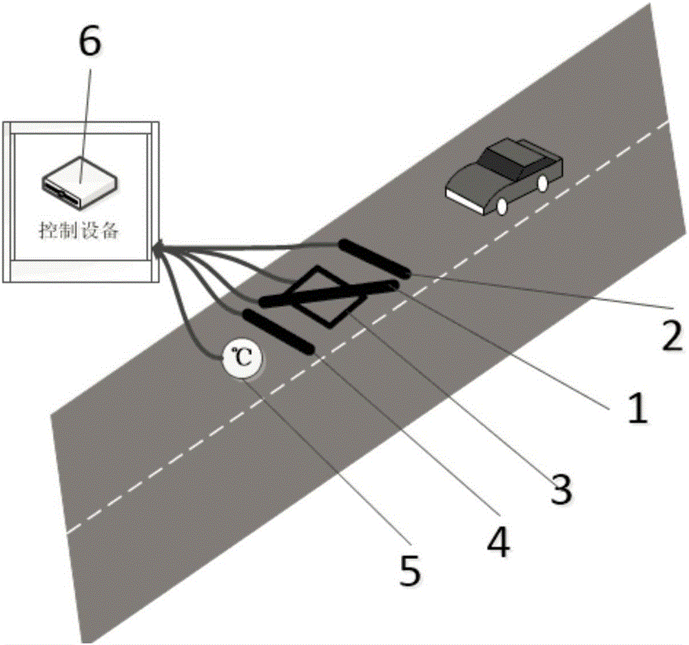
[0030] see figure 2 The main components and assembly position relationship of a kind of diagonal axis type (Z type) dynamic weighing system in this embodiment are shown. In this embodiment, a temperature sensor 5 is added in Embodiment 1. , with a diagonal piezoelectric axis 1, an input speed piezoelectric axis 2, a ground sense coil 3, an output speed piezoelectric axis 4, a temperature sensor 5, and a control device 6, wherein: the system includes a diagonal Piezoelectric axis 1, input speed piezoelectric axis 2, ground sense coil 3, output speed piezoelectric axis 4 and temperature sensor 5, and control device 6 connected with input speed piezoelectric axis 2 and output speed piezoelectric axis 4, control The device 6 calculates and displays the weight of the truck according to the electrical signals output by the diagonal piezoelectric axis 1 , the input speed piezoelectric axis 2 and the output speed piezoelectric axis 4 .

[0031] In this embodiment, the diagonal piezo...

Embodiment 3

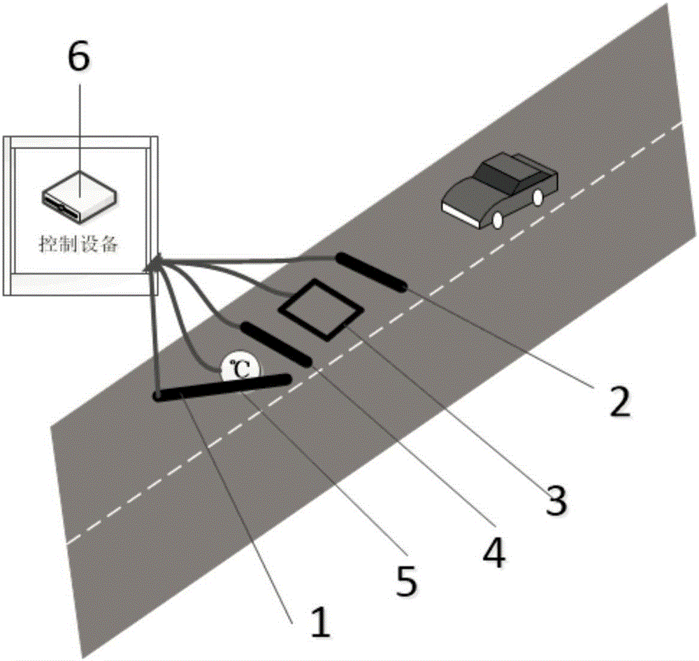
[0039] see image 3 It shows a diagonal axis type (Z type) dynamic weighing system in this embodiment, which is provided with a diagonal piezoelectric axis 1, an input speed piezoelectric axis 2, a ground sense coil 3, an output speed piezoelectric axis 4, and a temperature sensor 5. Control device 6, wherein: the system includes a diagonal piezoelectric axis 1, an input speed piezoelectric axis 2, a ground sensing coil 3, an output speed piezoelectric axis 4, and a temperature sensor 5 arranged in the weighing area, and is connected with the input The control device 6 connected to the speed piezoelectric axis 2 and the output speed piezoelectric axis 4, the control device 6 calculates and displays the load according to the electrical signals output by the diagonal piezoelectric axis 1, the input speed piezoelectric axis 2 and the output speed piezoelectric axis 4 car weight.

[0040] The present embodiment is based on embodiment 1-2. This embodiment also includes: the ground ...


PUM


Abstract

The invention provides a diagonal axis type dynamic weight measurement system and a diagonal axis type dynamic weight measurement method. The system comprises a diagonal piezoelectric axis, a driving-in speed piezoelectric axis and a driving-out speed piezoelectric axis which are arranged in a weight measurement area, and a control device which is connected with the diagonal piezoelectric axis, the driving-in piezoelectric axis and the driving-out speed piezoelectric axis. The control device calculates the weight of a truck according to electrical signals output by the diagonal piezoelectric axis, the driving-in piezoelectric axis and the driving-out speed piezoelectric axis, and displays the weight of the truck. The method comprises the following steps: the time difference is calculated according to two voltage curve peaks obtained when the two front wheels of a truck in a measurement area drive into the driving-in speed piezoelectric axis and the driving-out speed piezoelectric axis, and the speed of the truck is determined; the positions of the wheels are calculated according to the time difference between the two peaks of the front wheels obtained when the two front wheels drive into the diagonal piezoelectric axis; and the control device establishes a relevant database based on the peak area, truck speed, wheel position and ambient temperature obtained through integration of the voltage curve peaks acquired by the two front wheels, the driving-in speed piezoelectric axis and the driving-out speed piezoelectric axis, and a voltage curve is calculated and corrected to get the weight of the truck. The system and the method are used in traffic overweight detection and industrial park anti-theft detection.

Description

technical field [0001] The invention belongs to the field of dynamic weight measurement, and in particular relates to a dynamic weight measurement system, in particular to a dynamic weight measurement system and method with diagonal piezoelectric axis correction. Background technique [0002] In dynamic weight measurement, dual piezoelectric axis + ground sense coil is the most commonly used dynamic weight measurement method. At present, the conventional dynamic weighing method is to calculate the vehicle speed through the piezoelectric peak time difference collected by the piezoelectric shaft at the entry speed and the exit speed, and then obtain the peak area by integrating the voltage curves of the piezo shaft at the entry speed and exit speed. Calculate the calibration curve according to the comparison data of peak area and vehicle weight measured in advance, and finally calculate the medium vehicle weight. In the actual test, due to the characteristics of the piezoelec...

Claims


Application Information

Patent Timeline
Patent Type & Authority Applications(China)
IPC IPC(8): G01G19/02G01G23/01
CPCG01G19/024G01G23/01
Inventor 王攀
Owner 辉因科技(北京)有限公司
Learn More