Camera module optical center position measuring method and system

A camera module and measurement method technology, applied in the optical field, can solve the problems of long consumption time, difficult production line detection, errors, etc., and achieve the effect of stable testing

Active Publication Date: 2017-05-10
TRULY OPTO ELECTRONICS
View PDF7 Cites 21 Cited by
  • Summary
  • Abstract
  • Description
  • Claims
  • Application Information

AI Technical Summary

Problems solved by technology

[0003] In the prior art, for the lens manufacturer, the position of the optical center of the lens is measured by the illuminance. The luminance at the optical center is the largest, and the luminance decreases in the form of a ring. Based on this, the optical center position is determined, but this method is affected by the illuminance of the light source The influence of uniformity, if the uniformity of the light so

Method used


Image

  • Camera module optical center position measuring method and system
  • Camera module optical center position measuring method and system
  • Camera module optical center position measuring method and system

Examples


Embodiment Construction

[0045] In order to enable those skilled in the art to better understand the technical solutions in the present invention, the technical solutions in the embodiments of the present invention will be clearly and completely described below in conjunction with the drawings in the embodiments of the present invention. Obviously, the described The embodiments are only some of the embodiments of the present invention, not all of them. Based on the embodiments of the present invention, all other embodiments obtained by persons of ordinary skill in the art without making creative efforts shall fall within the protection scope of the present invention.

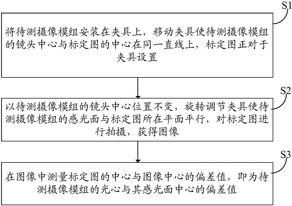
[0046] Please refer to figure 1 , an embodiment of the present invention provides a method for measuring the optical center position of a camera module, comprising the steps of:

[0047] S1: Install the camera module to be tested on the fixture, move the fixture so that the lens center of the camera module to be tested is on the same lin...


PUM


Abstract

The invention discloses a camera module optical center position measuring method and system; the method comprises the following steps: mounting a tested camera module on a clamp, moving the clamp so as to enable the lens center of the tested camera module to be on a same line with a labeled graph center, wherein the clamp can be translated and rotated, and the labeled graph is right opposite to the clamp; keeping the lens center position of the tested camera module to be unchanged, rotating and adjusting the clamp so as to enable a light-sensitive surface of the tested camera module to be parallel to a plane on which the labeled graph is located, shooting the labeled graph and obtaining an image; measuring the deviation value between the labeled graph center and the image center in the image, i.e., the deviation value between the optical center of the tested camera module and the light-sensitive surface center. The camera module optical center position measuring method and system can measure the optical center position of the tested camera module; the method is more stable and faster in testing when compared with a conventional method.

Description

technical field [0001] The invention relates to the field of optical technology, in particular to a method and system for measuring the optical center position of a camera module. Background technique [0002] The position of the optical center of the camera module has a certain influence on the imaging effect, especially for a dual camera module, if the optical center of the lens of the camera module is offset from the center of the photosensitive surface, the image synthesis effect will be deteriorated. Therefore, measuring the optical center position of the camera module becomes a necessary measure. [0003] In the prior art, for the lens manufacturer, the position of the optical center of the lens is measured by the illuminance. The luminance at the optical center is the largest, and the luminance decreases in the form of a ring. Based on this, the optical center position is determined, but this method is affected by the illuminance of the light source The influence of ...

Claims


Application Information

Patent Timeline
IPC IPC(8): G01M11/02
CPCG01M11/0221
Inventor 林挺李建华
Owner TRULY OPTO ELECTRONICS
Why Eureka
Try Eureka