Power switch control circuit applied to patrol robot

A technology for inspection robots and power switches, applied in computer control, general control systems, program control, etc., can solve problems such as system disorder, equipment damage, and robot data loss.

Inactive Publication Date: 2017-05-10
SICHUAN CHAOYING TECH CO LTD
View PDF6 Cites 3 Cited by
  • Summary
  • Abstract
  • Description
  • Claims
  • Application Information

AI Technical Summary

Problems solved by technology

The simple power-on and power-off of the original robot power switch can no longer meet the demand
The power-off method of simply and directly turning off the robot's power supply is likely to cause data loss of the robot, resulting in system data loss, system disorder, and equipment damage

Method used


Image

  • Power switch control circuit applied to patrol robot

Examples


Embodiment Construction

[0012] The following will clearly and completely describe the technical solutions in the embodiments of the present invention with reference to the accompanying drawings in the embodiments of the present invention. Obviously, the described embodiments are only some, not all, embodiments of the present invention. Based on the embodiments of the present invention, all other embodiments obtained by persons of ordinary skill in the art without making creative efforts belong to the protection scope of the present invention.

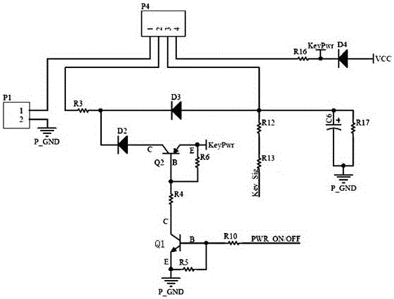
[0013] see figure 1 , in an embodiment of the present invention, a power switch control circuit applied to an inspection robot, the 2 pins of the relay control interface P1 are grounded, the 1st pin of the relay control interface P1 is connected to the 1st pin of the switch interface P4; the switch interface P4 The 2nd pin and the 3rd pin are connected through the resistor R3 and the diode D3, the 4th pin of the switch interface P4 is connected to the resistor...


PUM


Abstract

The present invention discloses a power switch control circuit applied to a patrol robot. The second foot of a control interface P1 of a relay is grounded, the first foot of the control interface P1 of the relay is connected with the first foot of a switch interface P4; and the second foot and the third foot of the switch interface P4 are connected with a diode D3 through a resistor R3, and the fourth foot of the switch interface P4 is connected with a resistor R16 and is connected in series with a diode D4. The circuit is provided with emergency switch, starting switch, software control switch and switch state monitoring functions. The power switch control circuit applied to the patrol robot can normally control the power supply of the patrol robot, can control the on-off of the power supply through the software control port, can set the cut-off time at will, can notify a robot upper computer system of the switching state, and can turn off the power supply of the patrol robot in the emergency condition through the emergency switch so as to reach the purpose of the multiple insurance of the safe management of the robot.

Description

technical field [0001] The invention relates to a control circuit, in particular to a power switch control circuit applied to an inspection robot. Background technique [0002] At present, with the continuous promotion of intelligent inspection robots, the requirements for inspection robots are getting higher and higher. Robots include PCs, industrial computers, and storage devices. Robots are equipped with more and more electronic devices and power supply systems. The more complex, with the continuous improvement of intelligence, the robot system needs to initialize the system configuration when it is powered on, the data collected by the robot needs a certain period of time to complete the data analysis and storage, and the corresponding data configuration needs to be saved when the robot is powered off. The lower robot needs emergency braking, and the upper computer system of the robot needs to know the current state of the robot switch. At the same time, it can control t...

Claims


Application Information

Patent Timeline
Patent Type & Authority Applications(China)
IPC IPC(8): G05B19/042
CPCG05B19/0423G05B2219/21119
Inventor 周谊
Owner SICHUAN CHAOYING TECH CO LTD
Why Eureka
Try Eureka