
Method and system for automatically obtaining physical positions of display units in wall splicing system

A technology of display unit and physical location, applied in the direction of digital output to display device, input/output process of data processing, electrical digital data processing, etc., can solve problems such as time-consuming, low work efficiency, and inability to realize automatic detection and configuration. Achieve the effects of avoiding manual configuration, improving configuration efficiency, and reducing hardware costs

Inactive Publication Date: 2017-05-10
GUANGDONG VTRON TECH CO LTD
View PDF4 Cites 17 Cited by
  • Summary
  • Abstract
  • Description
  • Claims
  • Application Information

AI Technical Summary

Problems solved by technology

This method is very time-consuming for large systems
[0003] In summary, the current processing method requires manual participation, and cannot realize automatic detection and configuration, and its work efficiency is low

Method used


Image

  • Method and system for automatically obtaining physical positions of display units in wall splicing system
  • Method and system for automatically obtaining physical positions of display units in wall splicing system

Examples


Embodiment 1

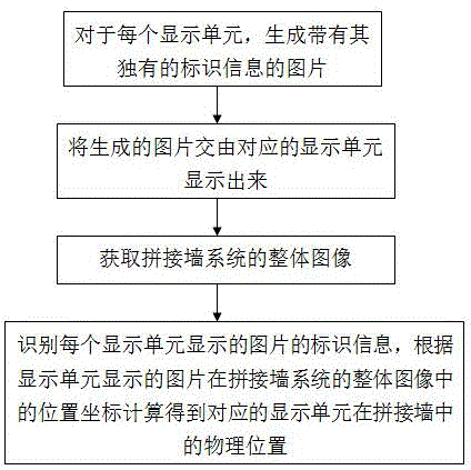
[0018] Such as figure 1 As shown, a method for automatically obtaining the physical location of display units in a video wall system, including:

[0019] S1. For each display unit, generate a picture with its unique identification information;

[0020] S2. Handing over the picture generated in S1 to the corresponding display unit for display;

[0021] S3. Obtain the overall image of the splicing wall system;

[0022] S4. Process the overall image of the video wall system, identify the identification information of the picture displayed by each display unit, and calculate the corresponding display unit according to the position coordinates of the picture displayed by the display unit in the overall image of the video wall system The physical location within the video wall.

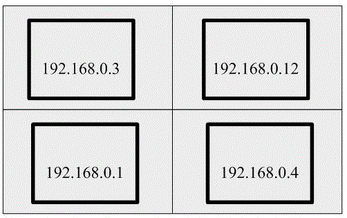
[0023] The identification information described in step S1 is an IP address.

[0024] This embodiment also includes modifying the IP address of each display unit to the address required by the user or r...

Embodiment 2

[0028] This embodiment is the same as Embodiment 1 except that the identification information described in step S1 is a row and column number randomly assigned to each display unit and each row and column number is unique.

Embodiment 3

[0030] An automatic acquisition system for the physical position of a display unit in a splicing wall system, including a picture generation module, a picture collection module and a picture processing module, the picture generation module is used to generate a picture with its unique identification information for each display unit picture, and the picture is displayed by the display unit, the picture acquisition module is used to obtain the overall image of the splicing wall system, and the image processing module is used to process the overall image of the splicing wall to identify the identity of each display unit information, and calculate the physical position of the corresponding display unit in the video wall according to the position coordinates of the picture displayed by the display unit in the overall image of the video wall system.

[0031] The identification information is an IP address.

[0032] The system in this embodiment is set in an external device with Int...


PUM


Abstract

The invention discloses a method and a system for automatically obtaining the physical positions of display units in a wall splicing system. The method comprises the following steps: for each display unit, generating pictures with unique identification information; displaying the generated pictures by corresponding display units; obtaining a whole image of the wall splicing system; processing the whole image of the wall splicing system, identifying the identification information of the picture displayed by each display unit, and calculating according to the position coordinates of the pictures displayed by the display units in the whole image of the wall splicing system so as to obtain the physical positions of the corresponding display units in the spliced wall. The physical position information of each display unit in the spliced water on the wall splicing system can be obtained, the method is convenient and quick without adding extra hardware software, the allocative efficiency can be improved during initial configuration of the system, and manual configuration of the units one by one is avoided.

Description

technical field [0001] The invention relates to the field of splicing walls, in particular to a method and system for automatically acquiring the physical position of a display unit in a splicing wall system. Background technique [0002] The splicing wall is composed of multiple display units. The display unit can display output on a single screen or multiple screens. The images displayed by each display unit are spliced ​​into a complete display screen. Therefore, to achieve correct multi-screen display, it is necessary to determine The physical location of each display unit on the overall video wall. The display unit will be configured with address information when it leaves the factory, such as IP address; after the splicing is completed, the address data of all display units can be obtained, but since the position of each display unit on the splicing wall is random during the splicing work, the system The correspondence between the address information of the display un...

Claims


Application Information

Patent Timeline
IPC IPC(8): G06F3/14
CPCG06F3/1446
Inventor 马先
Owner GUANGDONG VTRON TECH CO LTD
Learn More