Radome and antenna

A radome and antenna technology, which is applied to the antenna, radiation unit cover, electrical components, etc., can solve the problems of the decrease of the antenna cross-polarization ratio, the deterioration of the antenna's various indicators, and the complex reflection of electromagnetic waves, so as to improve the front-to-back ratio of the antenna. and cross-polarization ratio, improving the antenna radiation index, and solving the effect of the deterioration of the antenna index

Inactive Publication Date: 2017-05-10
COMBA TELECOM TECH (GUANGZHOU) CO LTD
View PDF5 Cites 2 Cited by
  • Summary
  • Abstract
  • Description
  • Claims
  • Application Information

AI Technical Summary

Problems solved by technology

The current mainstream beautifying antenna covers are mainly divided into square column, round column or fan-shaped column, but the indicators of the antenna in these types of special-shaped covers have deteriorated, especially the front-to-back ratio and cross-polarization ratio of the antenna.
Specifically, the reflection of electromagnetic waves in the heterosexual housing is more complicated than that of the general housing, which leads to the increase of the antenna’s backward radiation, that is, the deterioration of the front-to-back ratio; at the same time, when the electromagnetic energy inside the antenna housing increases, the antenna cross-polarization ratio and other indicators also increase. drop in magnitude
[0003] The current common optimization measures are to design the antenna separately for the cover used, such as developing the radiation unit for the corresponding cover, optimizing the shape of the reflector, or adding complex boundaries around the antenna, etc. However, the development efficiency of such solutions is low and the design cost is high. and poor consistency

Method used


Image

  • Radome and antenna
  • Radome and antenna
  • Radome and antenna

Examples


Embodiment 1

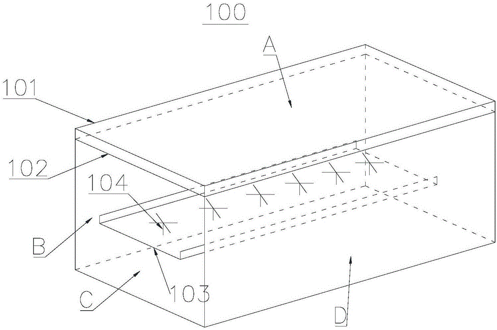
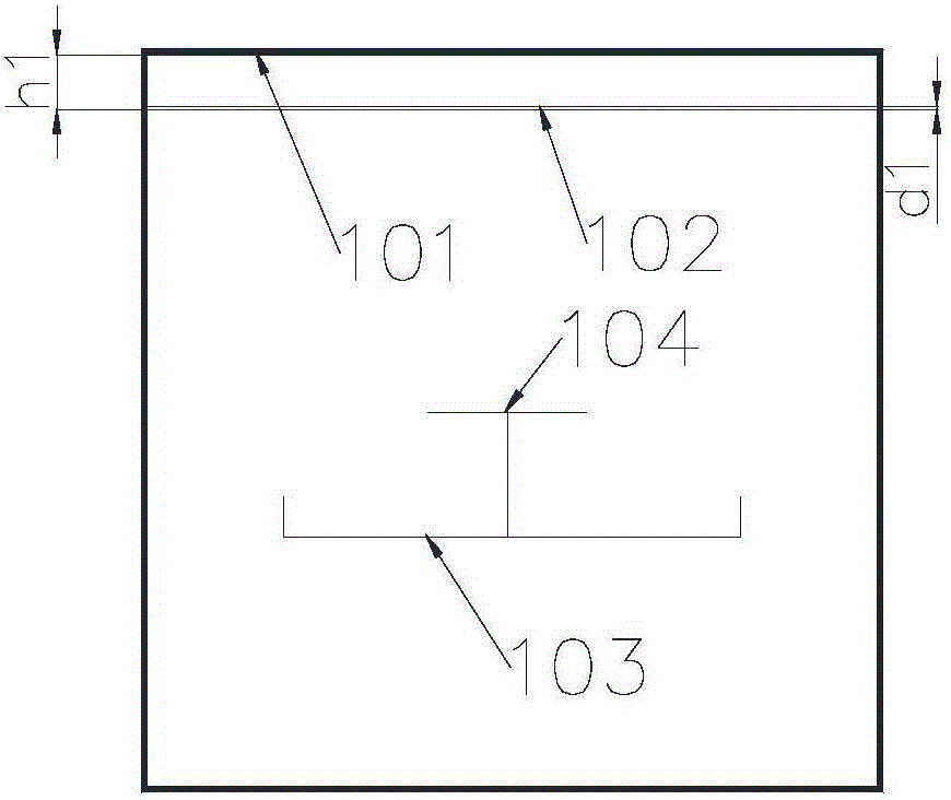
[0034] Embodiment one, such as Figure 1-2 As shown, when the antenna housing is in the shape of a square pillar, the antenna 100 is a square pillar-shaped beautifying antenna. The four surfaces of the antenna cover 101 , namely A, B, C, and D surfaces, are vertically connected to each other. The distance between the partition 102 and the antenna cover 101 is 0.2-0.3 times of the wavelength corresponding to the central frequency point of the antenna body of the antenna 100 . In this embodiment, the A surface is the main radiation surface of the antenna cover of the antenna 100, and the partition 102 is arranged inside the A surface and the distance h1 from the antenna cover 101 is 0.2 of the wavelength corresponding to the operating center frequency point of the antenna 100. -0.3 times. The thickness d1 of the partition 102 is less than 0.1 times the wavelength corresponding to the operating center frequency of the antenna 100 .

[0035] Such as Figure 3-4 As shown, when ...

Embodiment 2

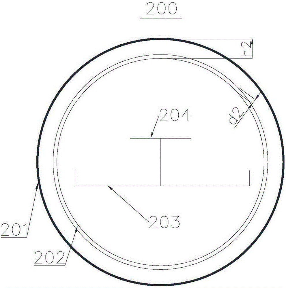
[0036] Embodiment two, such as image 3 As shown, the antenna 200 is surrounded by the radome. The partition 202 is disposed inside the antenna cover 201 , and the partition 202 and the antenna cover 201 are concentric circles. The distance h2 between the partition 202 and the antenna cover 201 is 0.2-0.3 times the wavelength corresponding to the working center frequency of the antenna 200, and the thickness d2 of the partition 202 is less than 0.2-0.3 times the wavelength corresponding to the working center frequency of the antenna 200. 0.1 times.

Embodiment 3

[0037] Embodiment three, such as Figure 4 As shown, the antenna 300 is surrounded by the radome. The distance between the partition plate 302 and the antenna cover 301 is 0.2-0.3 times of the wavelength corresponding to the central frequency point of the antenna body of the antenna 300 . In fact, in the cylindrical beautification antenna, the arc surface pointed by the front of the antenna body has greater electromagnetic wave energy than the arc surface pointed to by the back. Therefore, the main radiation surface of the antenna 300 is the antenna cover pointed by the front of the antenna body 301 semicircular area. The distance h3 between the partition 302 and the main radiation surface of the antenna cover 301 is 0.2-0.3 times the wavelength corresponding to the operating center frequency of the antenna 300 . The thickness d3 of the partition 302 is less than 0.1 times the wavelength corresponding to the operating center frequency of the antenna 300 .


PUM


Abstract

The invention provides a radome and an antenna. The radome comprises an antenna outer cover which is used for packaging an antenna body, and a separator plate which is arranged inside the antenna outer cover and is fixed to the antenna outer cover. According to the radome provided by the invention, through adding the separator plate at a position which is separated from a main radiation surface by a certain distance inside the antenna outer cover, energy of electromagnetic wave in the radome is reduced, and an integral radiation index of the antenna is improved. Particularly, a front-to-back ratio and a cross polarization ratio of the antenna are improved. Furthermore the radome has relatively high versatility in improving an antenna radiation index.

Description

technical field [0001] The invention relates to the field of beautifying antennas, in particular to a radome with a double-layer structure and an antenna using the radome. Background technique [0002] Due to the fear of antenna radiation, modern residents have voices of resistance to mobile communication base stations one after another. In order to hide the antenna, reduce complaints, and ensure coverage, beautifying the antenna came into being. The current mainstream beautifying antenna covers are mainly divided into square column, round column or fan-shaped column, but the indicators of the antenna in these types of special-shaped covers all deteriorate, especially the front-to-back ratio and cross-polarization ratio of the antenna. Specifically, the reflection of electromagnetic waves in the heterosexual housing is more complicated than that of the general housing, which leads to the increase of the antenna’s backward radiation, that is, the deterioration of the front-t...

Claims


Application Information

Patent Timeline
Patent Type & Authority Applications(China)
IPC IPC(8): H01Q1/42H01Q19/12
CPCH01Q1/42H01Q19/12
Inventor 李轶帆李明超赖展军周峰
Owner COMBA TELECOM TECH (GUANGZHOU) CO LTD
Why Eureka
Try Eureka