Multi-frequency base station antenna and its radiation unit

A technology of radiating unit and base station antenna, which is applied in the direction of independent antenna unit combination, radiating element structure, antenna, etc., can solve the problems of numerous components, difficult and complex location selection of base station antenna, etc., to improve radiation index and meet miniaturization , the effect of expanding the bandwidth

Active Publication Date: 2020-09-01
COMBA TELECOM TECH (GUANGZHOU) CO LTD
View PDF11 Cites 0 Cited by
  • Summary
  • Abstract
  • Description
  • Claims
  • Application Information

AI Technical Summary

Problems solved by technology

And as the public's awareness of the hazards of electromagnetic radiation deepens, the difficulty of selecting base station antenna sites and the shortage of site resources have become the bottleneck of network construction. Therefore, multi-frequency ultra-broadband has become the first choice for station construction, and 6-, 7-, and even 8-frequency antennas are becoming more and more popular. The more favored by operators, the antenna needs to support the frequency bands of 694-960MHz, 1710-2690MHz, 1427-2200MHz, and 1427-2690MHz at the same time. According to the general design method of the industry, the radiation unit needs to be adjusted according to the working frequency band. The number of ports increases and the number of supporting systems increases. A variety of radiating elements need to be designed in an antenna. The internal components of the antenna are numerous and complex, which brings challenges to production and versatility. Therefore, it is urgent to design a radiating element that can adjust itself according to the working frequency band. Adapt to adjust the working frequency to improve the versatility of the radiation unit and reduce the difficulty of multi-frequency antenna design

Method used


Image

  • Multi-frequency base station antenna and its radiation unit
  • Multi-frequency base station antenna and its radiation unit
  • Multi-frequency base station antenna and its radiation unit

Examples


Embodiment Construction

[0031] In order to enable those skilled in the art to better understand the solutions of the present invention, the following will clearly and completely describe the technical solutions in the embodiments of the present invention in conjunction with the drawings in the embodiments of the present invention. Obviously, the described embodiments are only It is a part of embodiments of the present invention, but not all embodiments. Based on the embodiments of the present invention, all other embodiments obtained by those skilled in the art without creative efforts fall within the protection scope of the present invention.

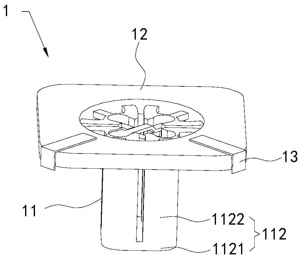
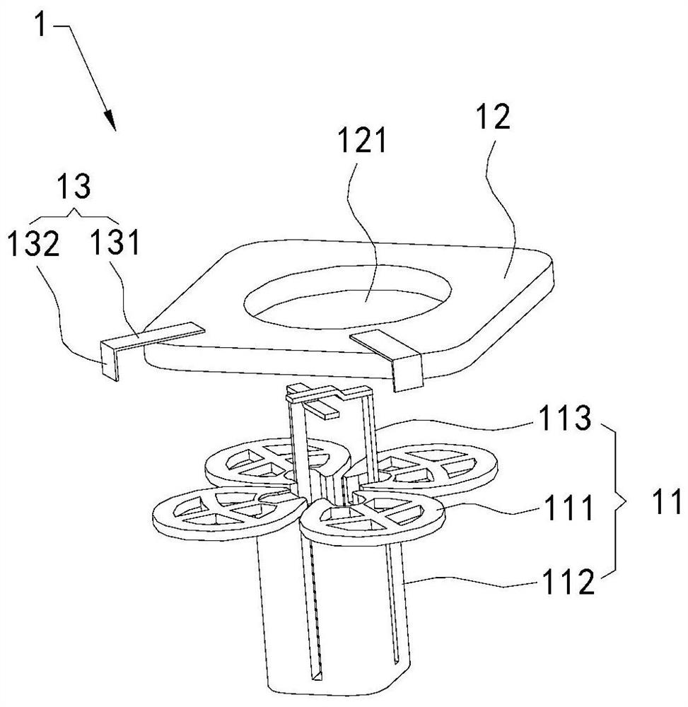
[0032] Please refer to figure 1 and figure 2 , the present invention provides a radiation unit 1 , comprising: a radiation unit main body 11 , a frequency adjustment unit 12 and an adjustment unit 13 .

[0033] The radiating unit main body 11 is a dual-polarized radiating unit, and is provided with four radiating arms 111 arranged in two pairs of orthogona...


PUM


Abstract

The present invention discloses a multiband base station antenna and a radiating unit thereof. The radiating unit comprises: a radiating unit body provided with at least one group of radiating arms, asupporting seat used for supporting the radiating arms, and a feed piece used for feed; and frequency adjustment units detachably covered and installed on the radiating arms and shielding a distal end of each of the radiating arms, wherein the frequency adjustment units are made of insulating materials and the working frequency of the radiating unit is changed by selecting materials with different sizes and / or different dielectric constants. By adding the frequency adjustment units on the radiating unit body, the working frequency of the radiating unit can be changed to satisfy the use needsof different frequency bands.

Description

technical field [0001] The invention relates to the technical field of mobile communication, in particular to a multi-frequency base station antenna and a radiation unit thereof. Background technique [0002] With the deepening of global 4G network construction, LTE network coverage is gradually diversified, and new frequency band requirements are constantly emerging. 3G and 4G network construction is mainly based on 1800MHz, 2100MHz, and 2600MHz. With the popularization of 4G networks, 4.5G has entered the planning stage, and operators need the network to support 3500MHz or be backward compatible with the frequency band requirements of 1400MHz. [0003] At present, mainstream high-frequency base station antennas support the wide frequency band of 1710-2170MHz and the ultra-wideband design and application of 1695-2700MHz, and the relative bandwidths are 23.7% and 45.7% respectively. Need to support 1400-2200MHz and 1400-2700MHz to meet the coverage requirements of global op...

Claims


Application Information

Patent Timeline
Patent Type & Authority Patents(China)
IPC IPC(8): H01Q1/12H01Q1/24H01Q1/36H01Q1/50H01Q5/10H01Q5/20H01Q5/321H01Q5/335H01Q5/50H01Q15/24H01Q21/00H01Q21/30
CPCH01Q1/12H01Q1/246H01Q1/36H01Q1/50H01Q5/10H01Q5/20H01Q5/321H01Q5/335H01Q5/50H01Q15/24H01Q21/0006H01Q21/30
Inventor 王强孙正辉李萌张鑫桢刘志军
Owner COMBA TELECOM TECH (GUANGZHOU) CO LTD
Why Eureka
Try Eureka