Phase balancing unit and power divider circuit phase balancing device

A technology of phase balance and power divider, which is applied to circuits, connecting devices, electrical components, etc., can solve problems such as phase dispersion, achieve the effects of reducing phase dispersion, improving radiation indicators, and realizing phase transmission characteristics

Pending Publication Date: 2017-02-08
COMBA TELECOM TECH (GUANGZHOU) CO LTD +1
View PDF9 Cites 4 Cited by
  • Summary
  • Abstract
  • Description
  • Claims
  • Application Information

AI Technical Summary

Problems solved by technology

[0005] The primary purpose of the present invention is to provide a phase balance unit that is beneficial to solve the phase dispersion problem between different output ports of the power divider circuit

Method used


Image

  • Phase balancing unit and power divider circuit phase balancing device
  • Phase balancing unit and power divider circuit phase balancing device
  • Phase balancing unit and power divider circuit phase balancing device

Examples


Embodiment 1

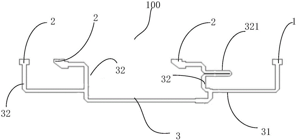
[0030] Such as figure 1 As shown, the embodiment of the present invention provides a phase balance unit 100, including an input port 1, a plurality of output ports 2 and a power divider circuit 3, the power divider circuit 3 has a main circuit 31 connected to the input port 1 and A plurality of output branches 32 are connected to the main circuit 31 and connected to each output port 2 one by one, and at least one of the output branches 32 is provided with a coupling transmission line 321 for changing the signal phase. Wherein, the power divider circuit 3 consists of a one-to-multiple power divider or a plurality of one-to-two power dividers connected in series or in parallel to form a one-to-multiple power division network.

[0031] One signal is input into the phase balance unit 100 from the input port 1 , flows through the main circuit 31 of the power divider circuit 3 and enters each output branch 32 , and then outputs from the output port 2 connected to the output branch 3...

Embodiment 2

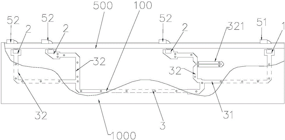
[0037] Such as figure 2 As shown, the present invention relates to a power divider circuit phase balance device 1000 (hereinafter referred to as "phase balance device 1000"), which uses the phase balance unit 100 of the first embodiment.

[0038] The phase balance device 1000 includes a housing 500, an input joint 51 and a plurality of output joints 52 disposed on the side wall of the housing 500, and the above-mentioned phase balance unit 100, the phase balance unit 100 is disposed in the housing 500, and The input port 1 is connected to the input connector 51 , and the multiple output ports 2 are connected to the multiple output connectors 52 in one-to-one correspondence.

[0039] Since the phase balance device 1000 of the present invention has the above-mentioned phase balance unit 100, the coupling of signals is performed by setting a close coupling transmission line 321 in one or more output branches 32, thereby changing the phase delay length of different frequency band...

Embodiment 3

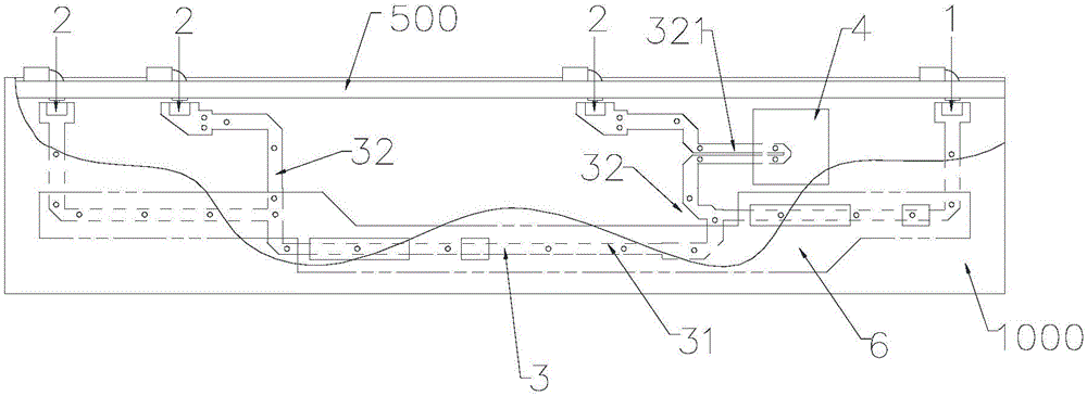
[0045] Such as Figure 4 As shown, this embodiment provides another implementation mode of the power divider circuit phase balance device, and its main feature is that: the power divider circuit phase balance device 1000 adopts a microstrip line structure, that is, the phase balance unit 100 is set in a 7 on the dielectric substrate. All the other are the same as embodiment one.


PUM


Abstract

The invention provides a phase balancing unit. The phase balancing unit comprises an input port, a plurality of output ports and a power divider circuit; the power divider circuit comprises a main circuit connected to the input port and a plurality of output branches which are connected to the main circuit and are connected to the output ports in one-to-one correspondence; and at least one output branch is provided with a coupling transmission line for changing a signal phase. The coupling transmission line is arranged on at least one output branch of the power divider circuit, which changes phase delay lengths of different frequency bands and achieves a goal that phase discrete type from the input port to each output port is improved in a certain frequency band phase. Besides, the invention also relates to a power divider circuit phase balancing device adopting the phase balancing unit.

Description

technical field [0001] The invention relates to the field of mobile communication, in particular to a phase balance unit and a power divider circuit phase balance device using the phase balance unit. Background technique [0002] In the mobile communication network coverage, the base station antenna is one of the key equipment of the coverage network. The main function of the base station antenna is signal coverage, and the pattern index to achieve signal coverage is particularly important. [0003] In base station antennas, base station antennas are divided into electrically adjustable base station antennas and non-electrically adjustable base station antennas. However, regardless of whether the base station antenna can be adjusted electrically, a power splitter is required, and the difference between them is only that the phase is adjustable or not. [0004] In addition, in a distributed circuit, the ratio of the size of the circuit to the working wavelength is basically ...

Claims


Application Information

Patent Timeline
Patent Type & Authority Applications(China)
IPC IPC(8): H01Q3/34H01P5/16
CPCH01P5/16H01Q3/34
Inventor 陈礼涛高彬刘培涛苏国生
Owner COMBA TELECOM TECH (GUANGZHOU) CO LTD
Why Eureka
Try Eureka