Low voltage switch, control method and device

A low-voltage switch and voltage technology, which is applied in the direction of circuit devices, emergency protection circuit devices, parts of emergency protection devices, etc., can solve problems such as difficult to meet equipment, large transformers, and lack of metering functions, so as to improve protection accuracy and the effect of metering accuracy

Active Publication Date: 2019-09-06
北京德威特电气科技股份有限公司
View PDF4 Cites 0 Cited by
  • Summary
  • Abstract
  • Description
  • Claims
  • Application Information

AI Technical Summary

Problems solved by technology

At present, the conventional low-voltage switchgear only has some simple protection functions and does not have a metering function. It is difficult to meet the needs of the equipment, and the protection accuracy is not high. and protect two sets of transformers, but due to the large size of the transformers, such a setting will lead to a large volume of low-voltage switches, which is difficult to actually use on site
If the metering and protection use the same set of transformers, the metering processor and the protection processor collect signals from the same transformer at the same time, and the final metering accuracy and protection accuracy will be relatively poor, especially below 0.1Ie (Ie is the rated current) And the protection accuracy above 6Ie cannot meet the actual protection accuracy requirements
[0003] In view of the technical problem that the low-voltage switch can only be used to protect the equipment in the prior art, no effective solution has been proposed yet

Method used


Image

  • Low voltage switch, control method and device
  • Low voltage switch, control method and device
  • Low voltage switch, control method and device

Examples


Embodiment 1

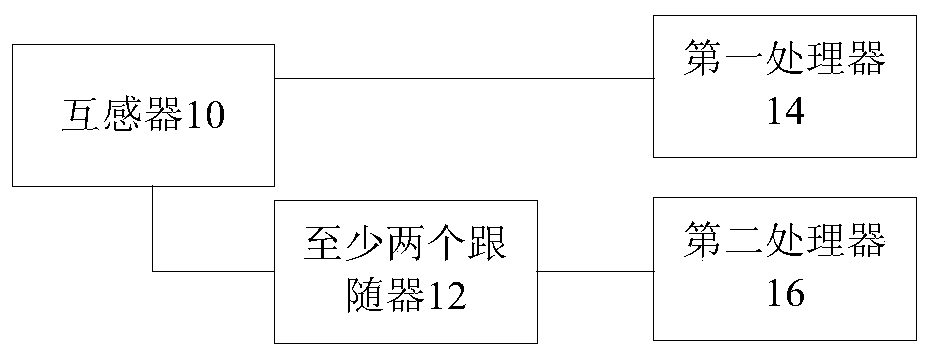
[0020] According to an embodiment of the present invention, an embodiment of a low voltage switch is provided, figure 1 is a schematic diagram of a low-voltage switch according to an embodiment of the present invention, such as figure 1 As shown, the low voltage switch includes:

[0021] The mutual inductor 10 is used to output differential signals.

[0022] At least two followers 12 are connected to the mutual inductors and are used to increase the driving capability of the differential signal.

[0023] The first processor 14 is connected with the transformer and is used for measuring preset parameters of the target object.

[0024] The second processor 16 is connected with at least two followers, and is used for protecting the target object according to the differential signals output by the at least two followers.

[0025] Specifically, the above-mentioned increase in the driving capability of the differential signal is used to indicate that the differential signal can b...

Embodiment 2

[0063] According to an embodiment of the present invention, an embodiment of a control method for a low-voltage switch is provided. It should be noted that the steps shown in the flow chart of the accompanying drawings can be executed in a computer system such as a set of computer-executable instructions, and , although a logical order is shown in the flowcharts, in some cases the steps shown or described may be performed in an order different from that shown or described herein.

[0064] Figure 6 It is a flowchart of an optional control method for a low-voltage switch according to an embodiment of the present invention. The low-voltage switch includes: a transformer, at least two followers connected to the transformer, a first processor connected to the transformer, and a At least two second processors connected to followers, such as Figure 6 As shown, the method includes the following steps:

[0065] Step S502, at least two followers receive the differential signal outpu...

Embodiment 3

[0074] According to an embodiment of the present invention, an embodiment of a low voltage switch is provided, Figure 7 It is a schematic diagram of a low-voltage switch control device according to an embodiment of the present invention. The low-voltage switch includes: a transformer, at least two followers connected to the transformer, and a first processor connected to the transformer and a second processor connected to said at least two followers, such as Figure 7 As shown, the control unit includes:

[0075] The enhancement module 70 is used for the at least two followers to receive the differential signal output by the transformer, and increase the driving capability of the differential signal.

[0076] The measurement module 72 is used for the first processor to measure preset parameters of the target object according to the differential signal output by the transformer.

[0077] A protection module 74, configured for the second processor to protect the target object...


PUM


Abstract

The invention discloses a low-voltage switch and a control method and device. The low-voltage switch comprises a mutual inductor, at least two followers, a first processor and a second processor, wherein the mutual inductor outputs differential signals; the followers are connected with the mutual inductor to enhance the driving capability of the differential signals; the first processor is connected with the mutual inductor to meter a preset parameter of a target object; and the second processor is connected with the at least two followers to protect the target object according to the differential signals output by the two followers. The technical problem that the low-voltage signal can only be used for protective equipment in the prior art is solved.

Description

technical field [0001] The invention relates to the field of low-voltage switches, in particular to a low-voltage switch, a control method and a device. Background technique [0002] With the development of technology, the requirements for low-voltage switchgear are getting higher and higher. At present, the conventional low-voltage switchgear only has some simple protection functions and does not have a metering function, which is difficult to meet the needs of the equipment, and the protection accuracy is not high. If the low-voltage switch is required to have metering and protection functions at the same time, in order to ensure accuracy, only metering And to protect two sets of transformers, but due to the large size of the transformers, such a setting will result in a large volume of low-voltage switches, which is difficult to actually use on site. If the measurement and protection use the same set of transformers, the measurement processor and the protection processor...

Claims


Application Information

Patent Timeline
Patent Type & Authority Patents(China)
IPC IPC(8): H02H1/00
Inventor 刘国营赵长兵李慧勇李增利张鉴刘兴昌常亮王敬仁欧阳强高龙集常红旗郝立鹏蒋玉红薛利民侯红民康颖张嗣勇李利霞
Owner 北京德威特电气科技股份有限公司
Why Eureka
Try Eureka