Automatic assembly equipment of motor assembly

An automatic assembly and component technology, applied in the direction of electric components, electrical components, electromechanical devices, etc., can solve the problems of strong operation tasks and low efficiency, and achieve the effect of facilitating the operation of a large number of workers and high work efficiency

Pending Publication Date: 2017-05-10
SUZHOU TANCOOM MECHANICAL & ELECTRICAL ENG
View PDF6 Cites 0 Cited by
  • Summary
  • Abstract
  • Description
  • Claims
  • Application Information

AI Technical Summary

Problems solved by technology

[0002] The engraving and tightening of the prior art requires workers to complete with jigs. Such an operation process is inefficient and the operation task is strong.

Method used


Image

  • Automatic assembly equipment of motor assembly

Examples


Embodiment Construction

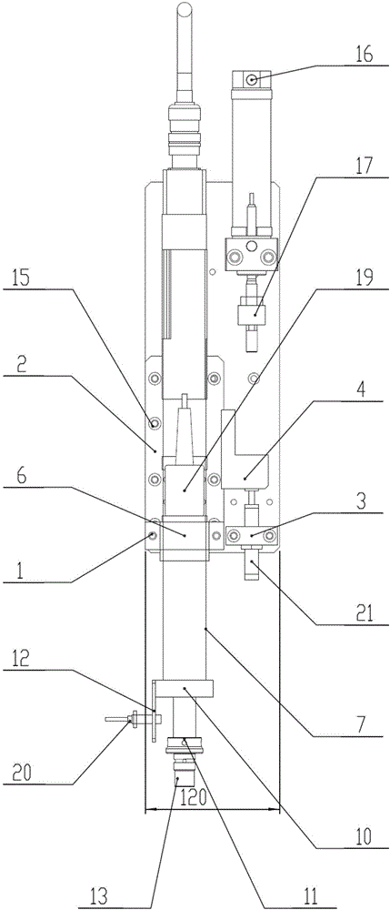
[0019] The present invention will be further described below in conjunction with the accompanying drawings and embodiments.

[0020] Such as figure 1 As shown, it is an automatic motor component assembly equipment according to the present invention, which includes a tightening base plate 1, an upper and lower sliding plate 2, a buffer seat 3, a floating joint seat 4, a gun seat 6, a gun head 7, a shaft card 10, and an induction block 11 , Proximity switch mounting plate 12, and sleeve 13.

[0021] The tightening base plate 1 includes two long sides along the vertical direction and two short sides along the transverse direction, the upper and lower sliding plates 2 extend vertically and are installed on the tightening base plate 1, and the buffer seat 3 is installed on the tightening base plate 1 and is located on the left side of the upper and lower slide plate 2, the floating joint seat 4 is installed on the tightening base plate 1 and above the buffer seat 3, the gun seat 6...


PUM


Abstract

The invention discloses automatic assembly equipment of a motor assembly. The automatic assembly equipment comprises a tightening bottom plate, an up-and-down sliding plate, a buffer seat, a floating connector base, a gun holder, a gun head, a shaft clamp, an induction block, an approach switch installation plate and a sleeve, wherein the tightening bottom plate comprises two long edges along the vertical direction and two short edges along the transverse direction; the up-and-down sliding plate extends along the vertical direction and is arranged on the tightening bottom plate; the buffer seat is arranged on the tightening bottom plate and located at the left side of the up-and-down sliding plate; the floating connector base is arranged on the tightening bottom plate and located above the buffer seat; the gun holder is arranged at the upper part of the gun head; the shaft clamp is arranged below the gun holder; the approach switch installation plate is arranged at the left side of the shaft clamp; and the sleeve is arranged below the induction block. The automatic assembly equipment of the motor assembly is high in work efficiency and a large number of operations of workers are facilitated.

Description

technical field [0001] The invention relates to an automatic assembly equipment for motor components, in particular to the specific structure of the automatic assembly equipment for motor components. Background technique [0002] The lettering and tightening in the prior art need to be completed by workers through jigs. Such an operation process is inefficient and requires heavy operation tasks. [0003] In view of the above-mentioned defects in the prior art, it is necessary to design an automatic assembly equipment for motor components. Contents of the invention [0004] The technical problem to be solved by the present invention is to provide an automatic assembly equipment for motor components. [0005] In order to solve the problems of the technologies described above, the technical solution of the present invention is: [0006] An automatic assembly equipment for a motor assembly, which includes a tightening base plate, an upper and lower sliding plate, a buffer se...

Claims


Application Information

Patent Timeline
Patent Type & Authority Applications(China)
IPC IPC(8): H02K15/00
CPCH02K15/00
Inventor 张晓勤陶方孙凯峰仝威
Owner SUZHOU TANCOOM MECHANICAL & ELECTRICAL ENG
Why Eureka
Try Eureka