

Projection method and electronic equipment
An electronic device and projection technology, applied in the field of projection, can solve problems such as distortion of projected content
- Summary
- Abstract
- Description
- Claims
- Application Information
AI Technical Summary
Problems solved by technology
Method used
Image

Examples
Embodiment 1
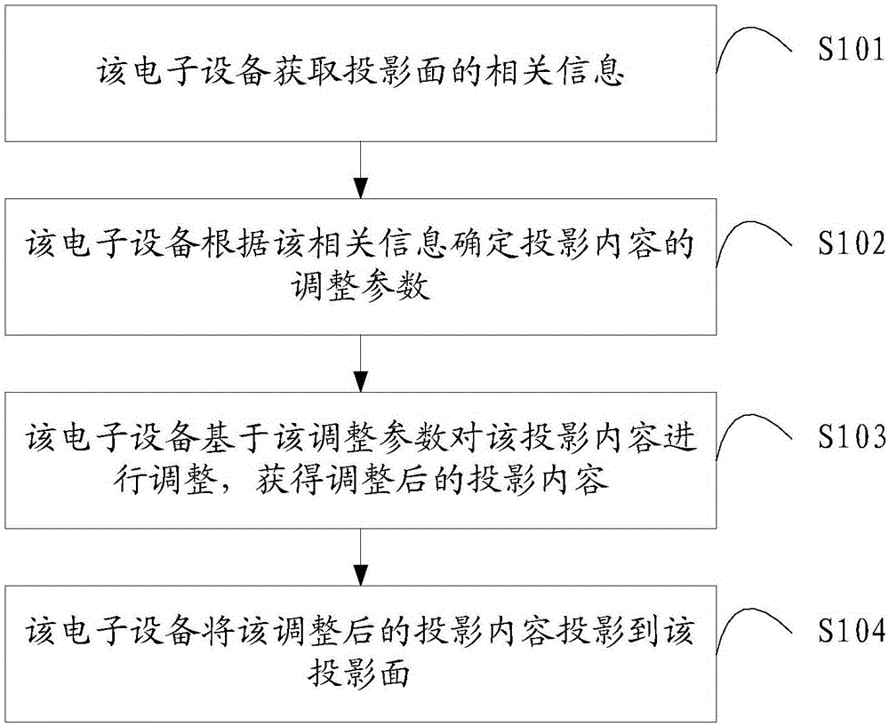
[0057] figure 1 Shown is a flowchart of a projection method provided by an embodiment of the present invention, which is applied to an electronic device. It is worth noting that the electronic device described in the embodiment of the present invention is an electronic device with a projection function, such as a projector , or a mobile phone with a projection function, etc. The projection method includes:
[0058] S101. The electronic device acquires relevant information of a projection surface.
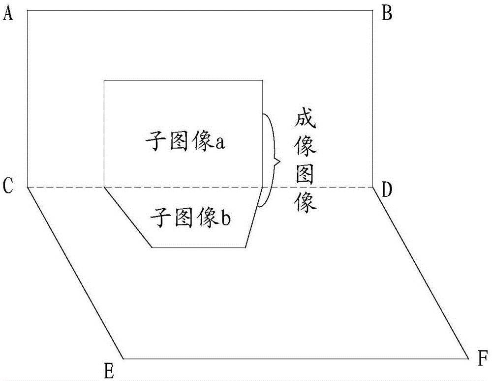
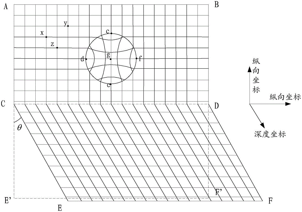
[0059] It is worth noting that the embodiments of the present invention may be applicable to a scenario where an electronic device is projected on an uneven projection surface, that is, the projection surface may have a concave portion or a convex portion. In a specific implementation process, the electronic device may include a first projection mode and a second projection mode, and when the electronic device detects that the user selects the first projection mode, it will perfor...
Embodiment 2
[0082] An embodiment of the present invention provides an electronic device 50 for implementing a projection method provided in Embodiment 1 of the present invention, such as Figure 5 As shown, the electronic device 50 includes:
[0083] An acquisition module 51, a processor 52 and a projection module 53;
[0084] The processor 52 is configured to acquire relevant information of the projection surface based on the acquiring module 51, determine adjustment parameters of the projection content according to the relevant information, adjust the projection content based on the adjustment parameters, and obtain the adjusted Project the content, and call the projection module 53 to project the adjusted projection content onto the projection surface.
[0085] Wherein, the relevant information acquired by the electronic device may be the concave-convex information of the projection surface itself, or may be an image of the projected content on the projection surface.
[0086] Theref...
Embodiment 3
[0098] The embodiment of the present invention provides another electronic device 60 for implementing the projection method provided in the first embodiment of the present invention, such as Figure 6 As shown, the electronic device 60 includes:
[0099] An acquisition unit 61, configured to acquire relevant information of the projection surface;
[0100] A determination unit 62, configured to determine adjustment parameters of projection content according to the related information acquired by the acquisition unit;
[0101] An adjustment unit 63, configured to adjust the projection content based on the adjustment parameters, to obtain adjusted projection content;
[0102] A projection unit 64, configured to project the adjusted projection content onto the projection surface.
[0103] Optionally, the acquiring unit 61 is specifically configured to acquire an imaging image of the projection content on the projection surface; the determining unit 62 is specifically configured ...
PUM
 Abstract
Description
Claims
Application Information