A method for assembling embedded components, an electronic equipment housing, and electronic equipment

A technology of electronic equipment and assembly method, which is applied in the direction of casing/cabinet/drawer components, etc., and can solve the problem of mismatch between the product casing and the external product casing

Active Publication Date: 2019-08-20
VIVO MOBILE COMM CO LTD
View PDF4 Cites 0 Cited by
  • Summary
  • Abstract
  • Description
  • Claims
  • Application Information

AI Technical Summary

Problems solved by technology

[0004] The invention provides an assembling method for an embedded sign, an electronic device casing and an electronic device, which solves the problem that the embedded product casing is easily separated from the external product casing when the product casing filling the embedded part is separated during the assembly process in the prior art. Issues where the product case inside the part does not match the product case outside

Method used


Image

  • A method for assembling embedded components, an electronic equipment housing, and electronic equipment
  • A method for assembling embedded components, an electronic equipment housing, and electronic equipment
  • A method for assembling embedded components, an electronic equipment housing, and electronic equipment

Examples


Embodiment 1

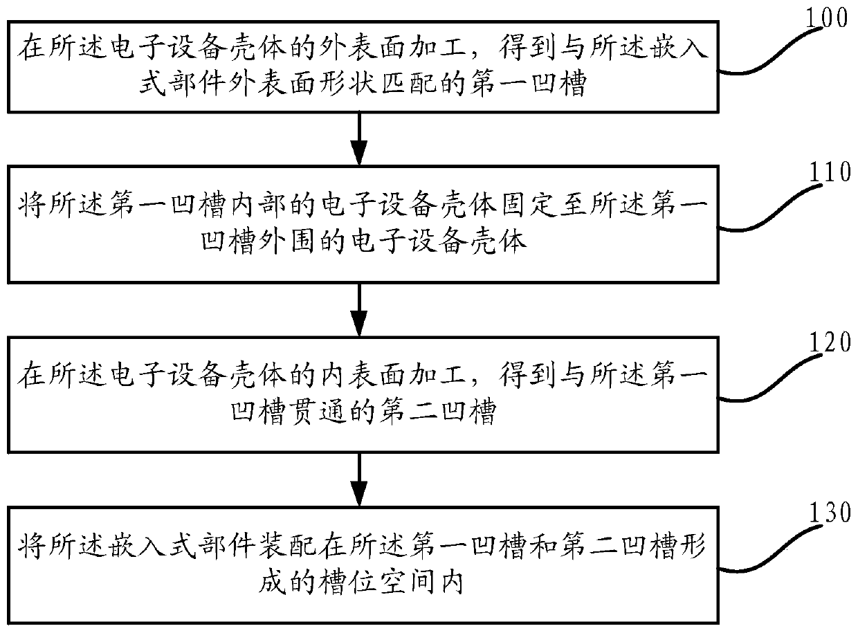
[0022] This embodiment provides a method for assembling embedded components, such as figure 1 As shown, the method includes: Step 100 to Step 130.

[0023] Step 100, machining the outer surface of the electronic device casing to obtain a first groove matching the shape of the outer surface of the embedded component.

[0024] On the outer surface of the electronic device casing, at the preset position for assembling the embedded component, a groove matching the shape of the embedded component is milled out by a CNC machine tool, as the first groove, for the receiving part The embedded component. The electronic equipment casing inside the first groove is the electronic equipment casing inside the embedded component after assembly; the electronic equipment casing around the first groove is the electronic equipment casing outside the embedded component after assembly body. Taking the O-shaped embedded part as an example, the shape of the processed first groove is O-shaped, and ...

Embodiment 2

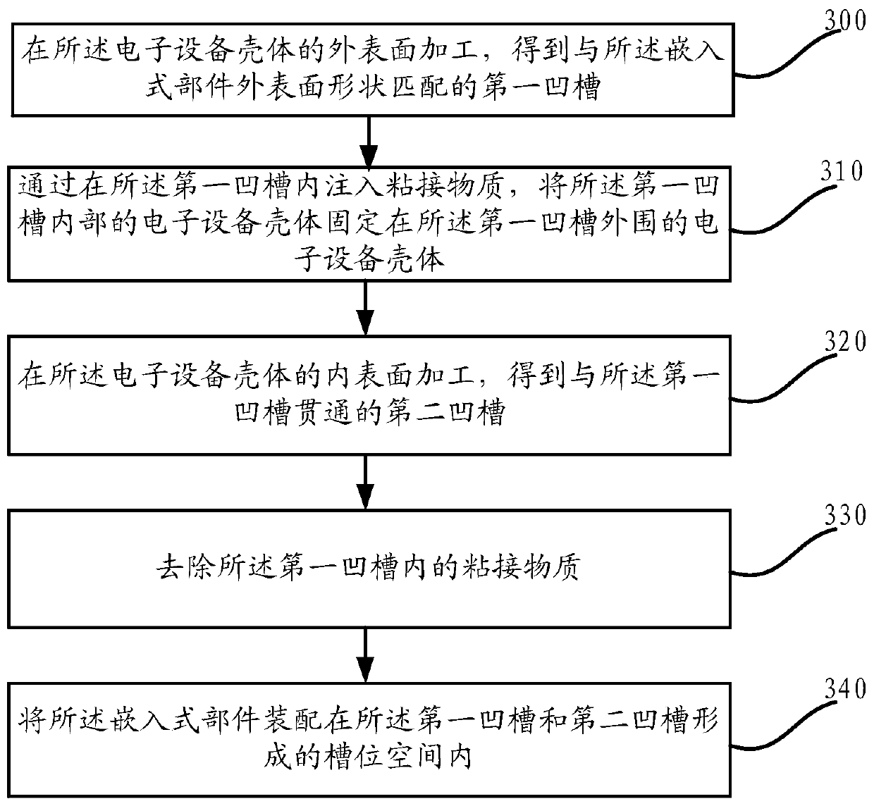
[0037] see image 3 , this embodiment provides a method for assembling embedded components, the method includes: Step 300 to Step 340 .

[0038] Step 300, process the outer surface of the electronic device housing to obtain a first groove matching the shape of the outer surface of the embedded component.

[0039] For a specific implementation manner of processing the first groove on the outer surface of the housing of the electronic device to match the shape of the outer surface of the embedded component, please refer to Embodiment 1, which will not be repeated here.

[0040] Step 310 , fixing the electronic device casing inside the first groove to the electronic device casing outside the first groove by injecting an adhesive substance into the first groove.

[0041] In this embodiment, it is taken as an example to fix the housing of the electronic device inside the first groove and the housing of the electronic device on the periphery of the first groove by injecting an adhe...

Embodiment 3

[0055] refer to Figure 5 Correspondingly, the embodiment of the present invention also discloses an electronic equipment casing 50 . The electronic device casing 50 includes: an embedded component 501 , and the embedded component 501 is assembled to the electronic device casing 50 according to the embedded component assembling method disclosed in the first embodiment and the second embodiment.

[0056] During specific implementation, firstly, the first groove matching the shape of the outer surface of the embedded component is processed on the outer surface of the electronic device housing; by injecting an adhesive substance into the first groove or injecting The outer surface of the equipment housing is covered with stickers to fix the electronic equipment housing inside the first groove to the electronic equipment housing on the periphery of the first groove; then, process the inner surface of the electronic equipment housing A second groove that passes through the first g...


PUM


Abstract

The invention provides an assembly method of an embedded part. The assembly method is applied to electronic equipment and belongs to the technical field of mobile communication. The method comprises the steps of processing an outer surface of an electronic equipment shell to obtain a first groove matched with the shape of the outer surface of the embedded part; fixing the electronic equipment shell in the first groove in the electronic equipment shell outside the first groove; processing an inner surface of the electronic equipment shell to obtain a second groove communicating with the first groove; and assembling the embedded part in a groove space formed by the first groove and the second groove. With the method disclosed by the embodiment of the invention, the problem that a product shell in the embedded part is not matched with an external product shell caused by after the product shell filled in the embedded part is easy to separate from the external product shell during the assembly process in the prior art is solved.

Description

technical field [0001] The invention relates to the technical field of mobile communication, in particular to an assembly method of an embedded component, an electronic equipment shell and the electronic equipment. Background technique [0002] In the process of product assembly, it is often encountered that it is necessary to assemble embedded components on the surface of the product, for example: setting a brand logo on the surface of the product to enhance the brand awareness of the product. Among the assembled embedded parts, the assembly method of the closed figure embedded parts is the most complicated. In the prior art, when assembling embedded components with closed graphics, in order to prevent the embedded components from falling, usually when processing the embedded component assembly holes on the outer product shell of the product, for the product shell filling the inside of the embedded components, The hanging table structure is processed to prevent the product...

Claims


Application Information

Patent Timeline
Patent Type & Authority Patents(China)
IPC IPC(8): H05K5/02
Inventor 胡柳见曾佑华朱家智
Owner VIVO MOBILE COMM CO LTD
Why Eureka
Try Eureka