Charging gun heat exchange structure and charging gun

A heat exchange structure and charging gun technology, applied in battery circuit devices, electrical equipment structural components, current collectors, etc., can solve problems such as large heat generation and hidden fire hazards of charging equipment, achieve low hidden dangers, avoid overheating and fire hazards Effect

Active Publication Date: 2017-05-10
SHENZHEN WOER HEAT SHRINKABLE MATERIAL +2
View PDF7 Cites 17 Cited by
  • Summary
  • Abstract
  • Description
  • Claims
  • Application Information

AI Technical Summary

Problems solved by technology

The short circuit includes the main line conductor, the cooling liquid and the metal casing of the liquid pump. The latter two will generate a large amount of heat when the short circuit occurs, and the heat generated by the liquid pump will cause fire hazards in the charging equipment.

Method used


Image

  • Charging gun heat exchange structure and charging gun
  • Charging gun heat exchange structure and charging gun
  • Charging gun heat exchange structure and charging gun

Examples


Embodiment Construction

[0025] Embodiments of the present invention will be described in detail below. It should be emphasized that the following description is only exemplary and not intended to limit the scope of the invention and its application.

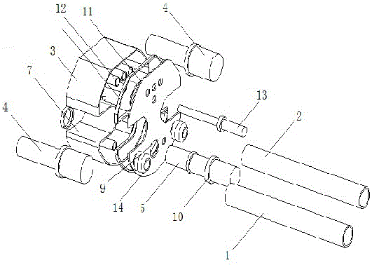
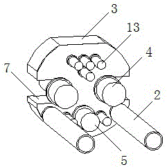
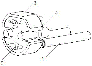
[0026] refer to Figure 1 to Figure 6 , in one embodiment, a charging gun heat exchange structure, including a heat exchange tank 3 arranged on the charging gun head 6, the heat exchange tank 3 is connected with the liquid inlet pipe 1 and the liquid outlet pipe 2, the main line terminal 4 and the ground wire terminal 5 pass through the heat exchange tank 3, and the cooling liquid flowing in from the liquid inlet pipe 1 flows through the heat exchange tank 3 and exchanges heat with the main wire terminal 4, and then flows from the liquid outlet pipe 2, the main line terminal 4 is electrically isolated from the cooling liquid in the heat exchange tank 3, and the ground wire terminal 5 is in electrical contact with the cooling liquid in the heat exchange...


PUM


Abstract

The invention discloses a charging gun heat exchange structure and a charging gun. The charging gun heat exchange structure comprises a heat exchange groove formed in the charging gun head; the heat exchange groove is connected with a liquid inlet pipe and a liquid outlet pipe; main wire terminals and a ground wire terminal pass through the heat exchange groove; a coolant which flows from the liquid inlet pipe flows through the heat exchange groove to perform heat exchange with the main wire terminals and then flows out of the liquid outlet pipe; the main wire terminals are set to be electrically isolated from the coolant in the heat exchange groove; and the ground wire terminal is set to be in electrical contact with the coolant in the heat exchange groove. By adoption of the charging gun heat exchange structure, the risk hidden danger caused by coolant leakage can be greatly lowered.

Description

technical field [0001] The invention relates to a heat exchange structure of a charging gun and a charging gun with the heat exchange structure. Background technique [0002] The cooling tube is arranged in the charging gun, and the terminal can be cooled by the liquid in the tube. The usual structure is to make a heat exchange tank, use a refrigeration tube to continuously provide refrigeration liquid to the heat exchange tank, and place the terminals outside the heat exchange tank to reduce the terminal temperature. [0003] Since the liquid pump that provides power to the coolant usually has a metal casing, and the metal casing will be grounded, once the heat exchange tank leaks liquid and the coolant comes into contact with the main line terminal, since the coolant is a conductive liquid, it will generate from Short circuit between the main line of high voltage and the ground of the metal casing of the liquid pump. The short circuit includes the main line conductor, th...

Claims


Application Information

Patent Timeline
Patent Type & Authority Applications(China)
IPC IPC(8): H05K7/20H02J7/00
CPCH02J7/0042H05K7/20218Y02T10/7072Y02T10/70Y02T90/12
Inventor 周诚智
Owner SHENZHEN WOER HEAT SHRINKABLE MATERIAL
Why Eureka
Try Eureka