
Device for an impedance tomograph

A technology of electrical impedance tomography and scanner, applied in the direction of diagnosis, application, diagnosis recording/measurement, etc., can solve the problems of wire line consumption, cost intensive, etc., and achieve the effect of good flexibility

Active Publication Date: 2017-05-10
DRAGERWERK AG
View PDF4 Cites 0 Cited by
  • Summary
  • Abstract
  • Description
  • Claims
  • Application Information

AI Technical Summary

Problems solved by technology

[0017] In the case of the above-mentioned star connection, it has been found that the corresponding electrical lines are often very complex and therefore very cost-intensive to produce

Method used


Image

  • Device for an impedance tomograph
  • Device for an impedance tomograph
  • Device for an impedance tomograph

Examples


Embodiment Construction

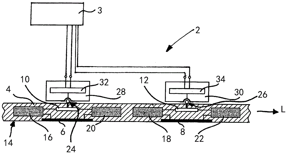
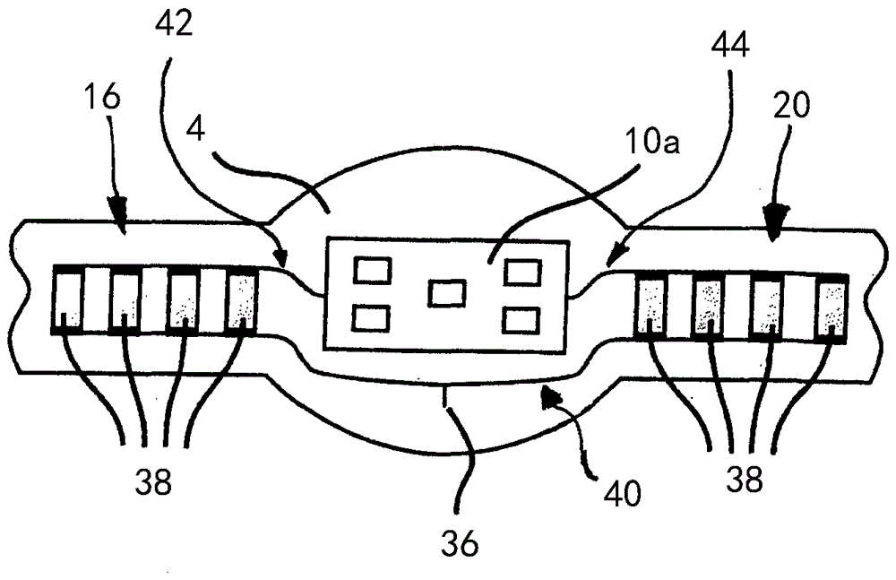
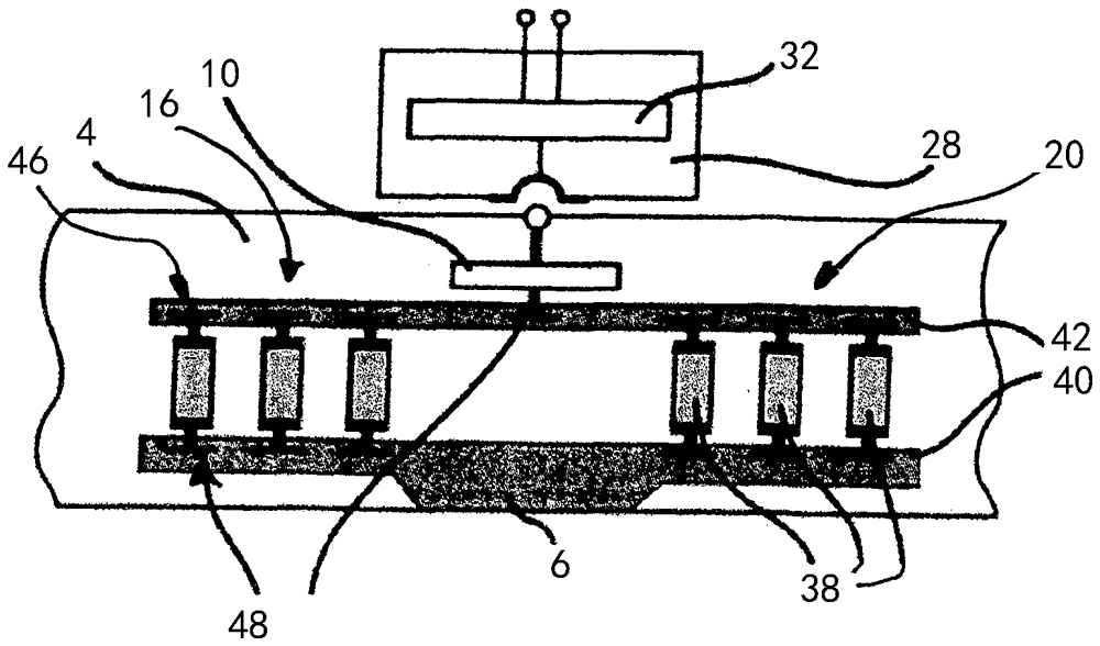
[0040] exist figure 1 In , a device 2 for an electrical impedance tomography scanner 3 according to the invention is shown. For this purpose, the device 2 includes an electrode carrier 4 . These are preferably so-called electrode strips. The electrode carrier 4 can thus be placed around the patient's body like a belt. The device 2 now includes a first skin electrode 6 and a second skin electrode 8 in order to transmit the electrical signals necessary for the impedance tomography scanner to the body or to receive electrical signals. The first and second skin electrodes 6 , 8 are arranged on the electrode carrier 4 at a distance from one another in the longitudinal direction L of the electrode carrier 4 . If the electrode carrier 4 is bent annularly, the skin electrodes 6 , 8 are arranged radially on the inside. The skin electrodes 6 , 8 are thus in direct contact with the patient's body and can thus ensure the desired signal transmission. as from figure 1 As is known from...


PUM


Abstract

The invention relates to a device (2) for an electrical impedance tomograph (3) with an electrode carrier (4), a first and a second skin electrode (6, 8) which are arranged on the electrode carrier (4) at a distance from each other and in the longitudinal direction L of the electrode carrier (4), as well as a first protection circuit (10) which is at least partially enclosed in the electrode carrier (4), wherein a second protection circuit (12) is provided, which is at least partially enclosed in the electrode carrier (4), the first protection circuit (10) being electrically connected to the first skin electrode (6) and the second protective circuit (12) being electrically connected to the second skin electrode (8).

Description

technical field [0001] The invention relates to a device for an electrical impedance tomography scanner, said device having an electrode carrier; first and second skin electrodes spaced apart from one another in the longitudinal direction of the electrode carrier arranged on the electrode carrier; and a first protection circuit at least partially embedded in the electrode carrier. Background technique [0002] Electrical diagnostic methods are often applied to patients in critical condition. It may be necessary here to use the defibrillator for a short period of time without sufficient time for the normal separation of the diagnostic device from the patient. There is thus a risk of destroying the diagnostic device due to overvoltage pulses. [0003] Defibrillation is the only effective and life-sustaining measure in life-threatening situations, as in the case of ventricular fibrillation or pulseless ventricular tachycardia. [0004] Any delay due to removal of the electro...

Claims


Application Information

Patent Timeline
Patent Type & Authority Applications(China)
IPC IPC(8): A61B5/053
CPCA61B5/0536A61B2562/043A61B2562/18A61N1/3931
Inventor F.扎特勒K.希尔塔夫斯基J.H.李
Owner DRAGERWERK AG
Learn More