Supercharge Your Innovation With Domain-Expert AI Agents!

Holing machine for limiting hole site

A technology for punching and limiting holes, which is applied in the field of punching machines, and can solve the problems of affecting the limiting sheet, unable to limit the fixing function of part 5, affecting the use of file managers, etc., and achieves the effect of convenient use

Inactive Publication Date: 2017-05-17
ZHONGSHAN HIGH END TECH SERVICE CO LTD
View PDF0 Cites 0 Cited by
  • Summary
  • Abstract
  • Description
  • Claims
  • Application Information

AI Technical Summary

Problems solved by technology

[0005] However, due to the height difference between the receiving surface 51 of the limiting part 5 and the placement surface 31 of the base 3, papers of different materials will be deformed by the height difference, and the actual punching position cannot be completely limited by the limiting part 5. There will be deviations in the punching position of the paper, which will make the files not neat and standardized when archiving, which will affect the use of the file manager
Moreover, the interior of the slot 41 cannot provide a good fixation effect on the limiting portion 5, and the limiting portion 5 will deviate in the radial direction of the slot 41, thereby affecting the limiting piece 52, so that it cannot form a good shape with the abutment surface 21. The vertical state of the paper will also affect the punching position of the paper

Method used


Image

  • Holing machine for limiting hole site
  • Holing machine for limiting hole site
  • Holing machine for limiting hole site

Examples


Embodiment Construction

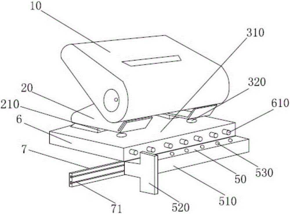
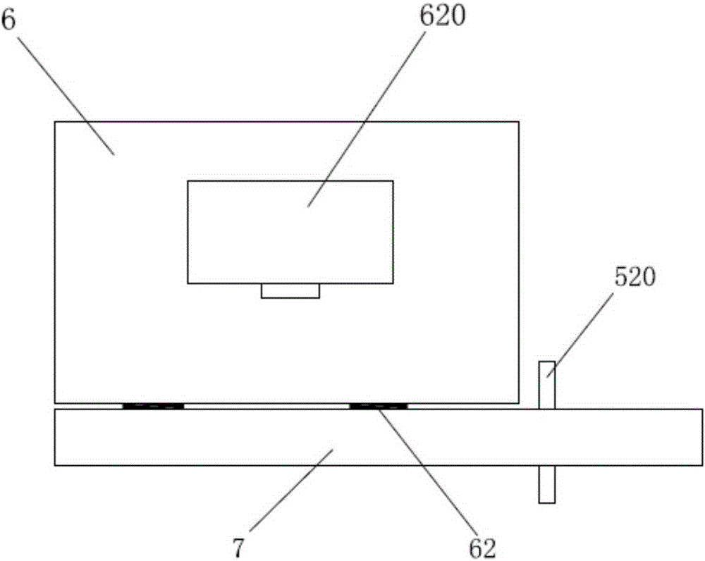
[0018] Such as figure 2 As shown, the supporting part 6 is a hollow structure, and the hollow structure allows the punching mechanism to pass through the through hole 320 to punch holes in the paper. A slide rail piece 7 is connected to the bottom edge of the front of the support portion 6 , and a slide groove 71 is provided on the surface of the slide rail piece 7 . The limiting part 50 is engaged with the sliding groove 71 and can slide along the slide rail piece 7. The end of the limiting part 50 is connected with a protruding limiting piece 520. The fronts of the support part 6 are spliced ​​together, and the height of the limiting part 50 is equal to the height of the support part 6, which enables the paper to be placed evenly on the placement surface 310 of the support part 6, and prevents paper of the same specification caused by the height difference. The problem that the punching position is different depending on the paper.

[0019] A plurality of protruding limit...


PUM


Abstract

The invention relates to a holing machine, in particular to the holing machine for limiting a hole site. The holing machine for limiting the hole site comprises a pressing part, a carrying part and a supporting part. The supporting part is of a hollow structure. A holing mechanism is arranged in the carrying part. The supporting part is provided with through holes corresponding to the holing mechanism. A sliding rail piece is connected with the bottom edge of the front of the supporting part in a riveting mode. A sliding groove is formed in the surface of the sliding rail piece. The sliding rail piece is connected with a limiting part which is connected with the sliding groove in a clamping mode and can slide along the sliding rail piece. A protruding limiting piece is connected with the end of the limiting part. The limiting part can rotate along with the sliding rail piece and is connected with the font of the supporting part in a splicing mode, and the height of the limiting part is equal to the height of the supporting part. The problem that an existing holing machine cannot well limit the holing site, so that deviation occurs in the holing site of paper with same size is solved. The holing machine better limiting the holing site is provided, convenient to use and simple and practical.

Description

[0001] 【Technical field】 [0002] The invention relates to a punching machine, in particular to a punching machine with hole positions limited. [0003] 【Background technique】 [0004] The punching machine can easily and quickly punch holes in the paper, which is very convenient for the storage and filing of paper documents, so it is widely used in offices and other places. Such as figure 1 As shown, the existing punching machine includes a limiting portion 5 for limiting the punching position of the paper, and an abutting surface 21 located on the receiving portion 2 and set perpendicular to the ground. The abutting surface 21 and the restricting piece 52 of the restricting part 5 are in a state matching the vertical angle of the paper, and the punching mechanism completes the punching of the paper. [0005] However, due to the height difference between the receiving surface 51 of the limiting part 5 and the placing surface 31 of the base 3, papers of different materials wil...

Claims


Application Information

Patent Timeline
Patent Type & Authority Applications(China)
IPC IPC(8): B26F1/02B26D7/01
Inventor 张丹
Owner ZHONGSHAN HIGH END TECH SERVICE CO LTD
Features
  • R&D
  • Intellectual Property
  • Life Sciences
  • Materials
  • Tech Scout
  • Unparalleled Data Quality
  • Higher Quality Content
  • 60% Fewer Hallucinations
Learn More