Composite floor jointly stressed by corrugated steel and cast-in-place reinforced concrete

A technology of reinforced concrete and corrugated steel plates, applied to floors, building components, buildings, etc., can solve problems such as time-consuming, laborious and cumbersome procedures

Active Publication Date: 2017-05-17
HUBEI BIEYIGE STEEL STRUCTURE TECH DEV
View PDF7 Cites 1 Cited by
  • Summary
  • Abstract
  • Description
  • Claims
  • Application Information

AI Technical Summary

Problems solved by technology

[0002] At present, the construction process of cast-in-place slabs in the field of construction engineering is: laying the slab base formwork - installing binding steel bars on the base formwork - pouring concrete - dismantling the slab base formwork - plastering and whitewashing the bottom of the slab and other decoration processes. The process is cumbersome and time-consuming.

Method used


Image

  • Composite floor jointly stressed by corrugated steel and cast-in-place reinforced concrete
  • Composite floor jointly stressed by corrugated steel and cast-in-place reinforced concrete
  • Composite floor jointly stressed by corrugated steel and cast-in-place reinforced concrete

Examples


Embodiment Construction

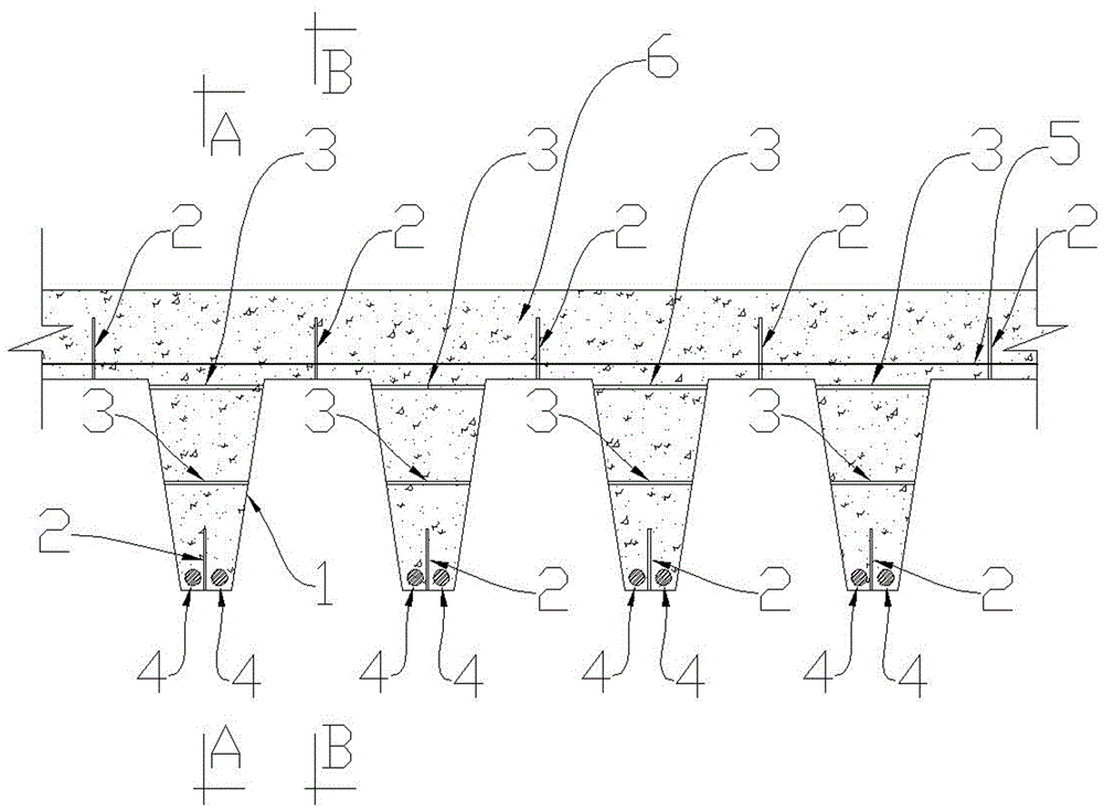
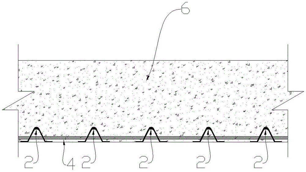
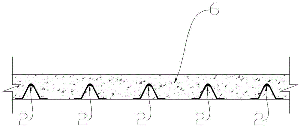
[0014] First, the single corrugated steel plate 1, the anchoring steel bar 2 and the tie bar 3 are processed and welded in the factory, and then multiple single corrugated steel plates 1 are installed on the construction site and the longitudinal joint is installed at the longitudinal joint of the two corrugated steel plates 1 Plate 12 and ensure that the cast-in-place concrete at the joint will not leak grout, place the longitudinal stress main reinforcement 4 in the groove at the bottom of the corrugated steel plate 1, place the transverse stress reinforcement 5 at the upper end of the corrugated steel plate 1, and finally pour the cast-in-place concrete 6 , the entire construction process is completed; it needs to be explained: when the floor slab is subjected to external loads, the anchoring steel bars 2 can prevent slippage and separation between the corrugated steel plate 1 and the cast-in-place concrete 6, and can ensure that the corrugated steel plate 1 and the cast-in-p...


PUM


Abstract

The invention provides a composite floor jointly stressed by corrugated steel and cast-in-place reinforced concrete, and is mainly used in the field of architectural engineering. The composite floor is high in construction speed and simple in working procedure; the composite floor is mainly composed of a corrugated steel 1, an anchor steel bar 2, a steel tie bar 3, and cast-in-place reinforced concrete 6; the main working principle is that when the floor bears an external load, the anchor steel bar 2 can prevent the part between the corrugated steel 1 and the cast-in-place reinforced concrete reinforced 6 from slip and separation, wherein the corrugated steel 1 plays the role of a stressed steel bar at the moment; left and right webs 7 of the corrugated steel 1, a lower wave plate 8 and the cast-in-place reinforced concrete 6 are combined into a reinforced concrete joist, the steel tie bar 3 ties the left and right webs 7 of the corrugated steel 1, thus when the reinforced concrete joist bears the external load on the floor, the cast-in-place reinforced concrete 6 cannot deform, in fact, the left and right webs 7 and the lower wave plate 8 play the role of stirrup of a reinforced concrete beam, and therefore, the corrugated steel 1 and the cast-in-place reinforced concrete 6 can completely jointly work and resist external force.

Description

technical field [0001] The invention is mainly used for cast-in-place floor slabs in the field of construction engineering. Background technique [0002] At present, the construction process of cast-in-place slabs in the field of construction engineering is: laying the slab base formwork - installing binding steel bars on the base formwork - pouring concrete - dismantling the slab base formwork - plastering and whitewashing the bottom of the slab and other decoration processes. The process is cumbersome and time-consuming. . Contents of the invention [0003] The present invention overcomes the above-mentioned shortcomings. It has fast construction speed, simple process, and under the same cross-sectional area, its strength and rigidity are much greater than ordinary floor slabs; It is composed of tie bars (3), longitudinal main bars (4), transverse bars (5), cast-in-place concrete (6), and longitudinal joint plates (12); the corrugated steel plate (1) consists of multipl...

Claims


Application Information

Patent Timeline
IPC IPC(8): E04B5/40
CPCE04B5/40
Inventor 彭宝安
Owner HUBEI BIEYIGE STEEL STRUCTURE TECH DEV
Why Eureka
Try Eureka